Modbus dip switch settings for the ld5000, Table 9: baud rate, Table 10: modbus slave address – RLE LD5000 User Manual
Page 81
User Guide: LD5000
Appendix A: Modbus Communication
www.rletech.com 970.484.6510
73
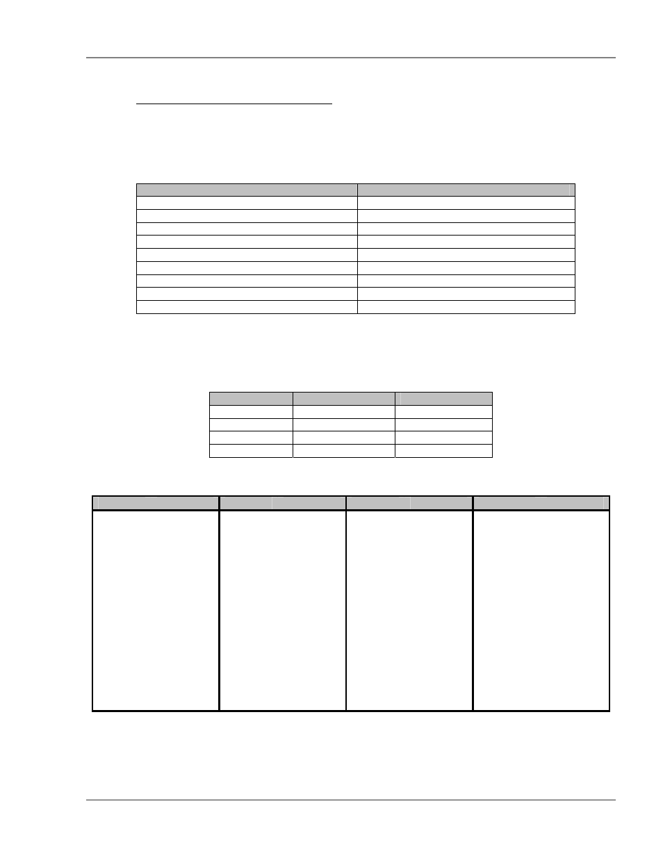
A-2.4 Function 16: Preset Multiple Registers
To set multiple LD5000 parameter values, the master must send a Preset Multiple Registers request packet. The
Preset Multiple Register request packet specifies a starting register, the number of registers, a byte count and the
data to write to the registers. The register is numbered from zero (40001 = zero, 40002 = one, etc).
Table 8: Preset Multiple Registers Packet Structure
Preset Registers Request Packet
Preset Registers Response Packet
Slave Address (1 byte)
Slave Address (1 byte)
16 (Function code) (1 byte)
16 (Function code) (1 byte)
Start Register (2 bytes)
Start Register (2 bytes)
# of registers to write (2 bytes)
# of registers (2 bytes)
Byte Count (1 byte)
Crc Checksum (2 bytes)
Data (2 bytes)
…
…
Crc Checksum (2 bytes)
A-3
MODBUS DIP SWITCH SETTINGS FOR THE LD5000
Table 9: Baud rate
Baud Rate
SW2 – 5
SW2- 6
1200 Off Off
2400 Off On
9600 On Off
19200 On
On
Table 10: Modbus Slave Address
Address
SW2 (8..1)
Address
SW2 (8..1)
Address
SW2 (8..1)
Address
SW2 (8..1)
0
00000000 16
00010000 32
00100000 48
00110000
1
00000001 17
00010001 33
00100001 49
00110001
2
00000010 18
00010010 34
00100010 50
00110010
3
00000011 19
00010011 35
00100011 51
00110011
4
00000100 20
00010100 36
00100100 52
00110100
5
00000101 21
00010101 37
00100101 53
00110101
6
00000110 22
00010110 38
00100110 54
00110110
7
00000111 23
00010111 39
00100111 55
00110111
8
00001000 24
00011000 40
00101000 56
00111000
9
00001001 25
00011001 41
00101001 57
00111001
10 00001010
26 00011010
42 00101010
58 00111010
11 00001011
27 00011011
43 00101011
59 00111011
12 00001100
28 00011100
44 00101100
60 00111100
13 00001101
29 00011101
45 00101101
61 00111101
14 00001110
30 00011110
46 00101110
62 00111110
15 00001111
31 00011111
47 00101111
63 00111111
• For address’s 64 –127, set sw1 # 7 to on then subtract 64 from the address and use the table.
• For address’s 128 –191, set sw1 #7 off, # 8 to on then subtract 128 from the address and use the
table.
• For address’s 192 –254, set sw1 #7 &. 8 to on then subtract 192 from the address and use the above table.