Connections and settings, Chapter 2: connections and settings, Figure 2-1 ld5000 leak detection boards – RLE LD5000 User Manual
Page 12
Chapter 2: Connections and Settings
User Guide: LD5000
4 970.484.6510
www.rletech.com
CHAPTER 2: CONNECTIONS AND SETTINGS
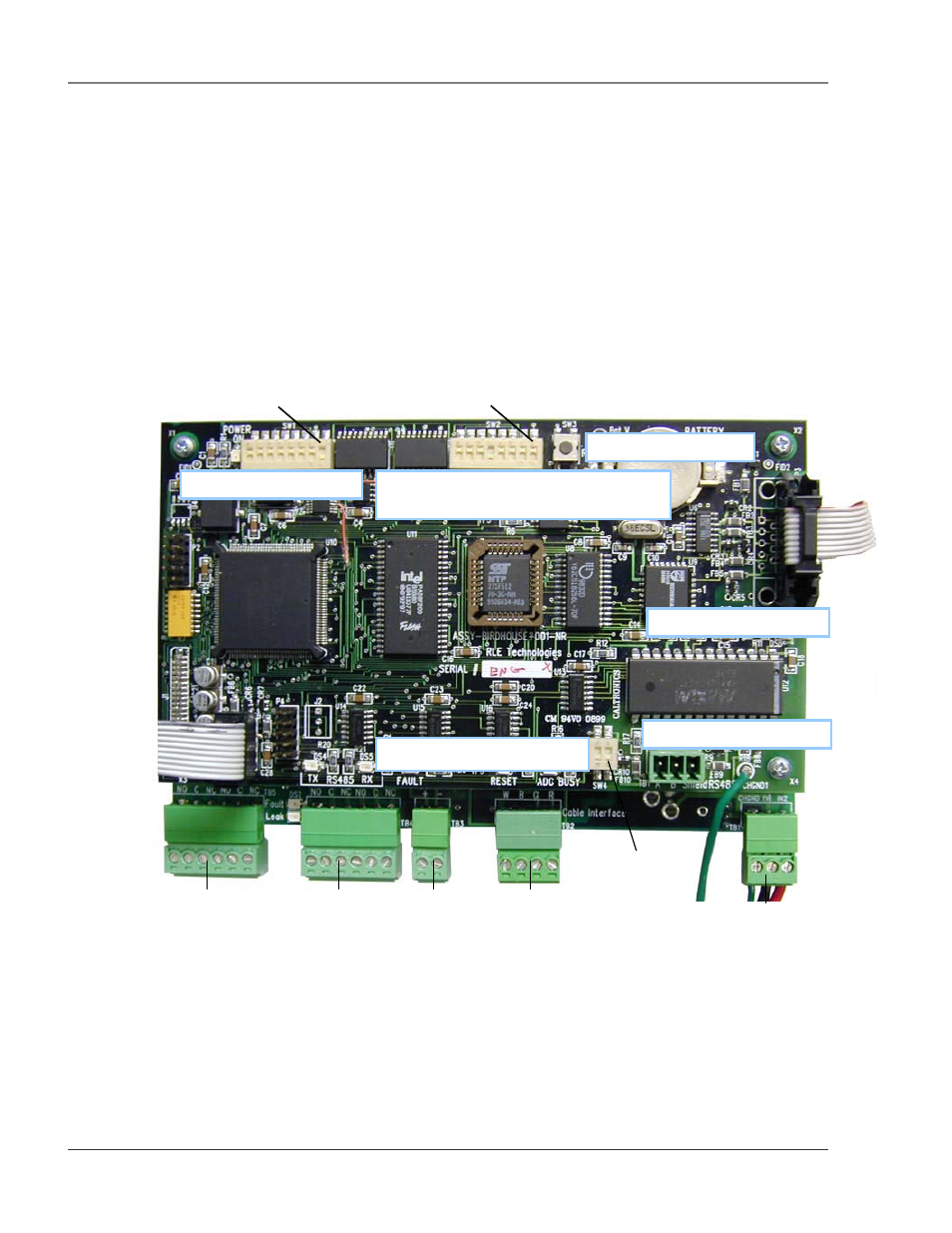
The LD5000 is comprised of three boards. All three boards are accessed when the device’s front cover is
opened. The display board is located on the inside of the door. The microprocessor board is stacked on top
of the leak detection board. Since the leak detection board is longer than the microprocessor board, the
connectors on the leak detection board extend past the end of the microprocessor board. These two boards
are secured to the inside of the unit.
The connectors on the leak detection board, found at the bottom of the following photograph, are labeled
TB1 through TB5. The connectors on the microprocessor board are labeled TB1 and P3. The switches on
the microprocessor board are labeled SW1 through SW4.
Figure 2-1 LD5000 Leak Detection Boards
SW1 – RS-485 Address
SW2 – RS-485 and RS-232 Baud Rate,
Display, and 4-20mA Output Settings
SW4 – Termination Setting
P3 – RS-485 Connector
SW3 – Reset Switch
TB1 – RS-485
Pin 1
Pin 1
Pin 1
TB4 – Fault/Leak
Relay Outputs
TB5 – Fault/Leak
Relay Outputs
TB2 – Cable
Interface
TB3 –
4-20mA
Output
TB1 – 24V
Input Power