Installation, Installing the unit, Connecting the water leak detection cable – RLE LD5000 User Manual
Page 17: Securing cable to the floor, Chapter 3: installation
User Guide: LD5000
Chapter 3: Installation
www.rletech.com 970.484.6510
9
CHAPTER 3: INSTALLATION
3-1
INSTALLING THE UNIT
The LD5000 is a wall mounted device. To secure the device to the wall, first remove the aluminum back
panel and all electronics from the enclosure. There are knockouts on the top and bottom of the enclosure
designed to accommodate .5” conduit. Remove as many as necessary. There are two holes in the top back
of the unit spaced 10.5” apart. Use drywall anchors to secure the unit to the wall. Put two more drywall
anchors through the two holes in the bottom back of the unit. Reinstall the back panel and reconnect the
electronics.
3-2
CONNECTING THE WATER LEAK DETECTION CABLE
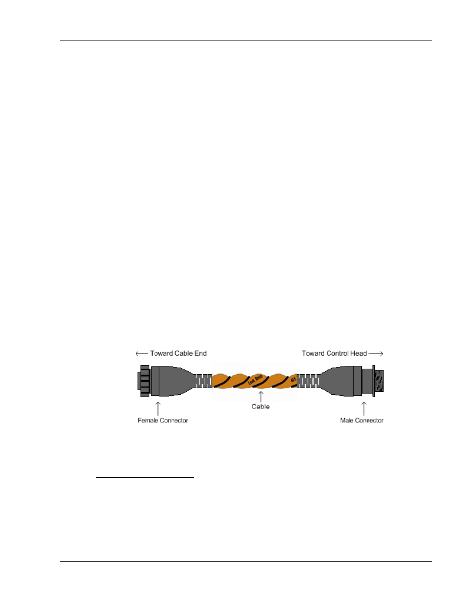
The LD5000 is packaged with a 15’ length of leader cable. One end of this leader cable connects into the
LD5000. This end of the cable is finished with a terminal connector. The other end features a mating
connector which connects with the leak detection cable. The end of the cable is finished with a removable
end terminator.
Attach (clip) the plastic EMI Suppression core to the 15’ leader cable. The plastic core should slide freely
once it is placed on the cable. Make sure the core is located close to the end of the leader cable that
attaches to the LD5000 terminal block connection (TB2). Connect the 15' leader cable with the EMI
Suppression core to the LD5000; plug the terminal connector into the cable interface terminal block TB2.
From left to right, with the screws of the connector facing up, the wires that screw into the terminal
connector should be colored white, black, green, and red. If the terminal connector is removed from the
end of the cable, make sure the wires are in this same order when the connector is reapplied.
Once the leader cable is plugged into the terminal blocks, it is ready to be connected to the leak detection
cable. To do this, unscrew the end terminator from the end of the leader cable. Attach the first length of
water leak detection cable to the leader cable. Route the water leak detection cable according to the cable
layout diagram, if provided. Lay the cable according to the following guidelines. Secure the end
terminator on the unoccupied end of the leak detection cable.
Figure 3-1 Water Leak Detection Cable
3-2.1 Securing Cable to the Floor
Secure the cable to the floor with either J-clips or one of the other approved methods shown in Figure 3-2
Cable Installation Methods. J-clips are the manufacturer’s recommended installation method and can be
installed as follows:
• Place one J-clip every three feet along the length of the water leak detection cable and one at each
turn of the cable.