20ma output testing, Chapter 4: 4-20ma output testing, Figure 4-1 4-20ma testing – RLE LD5000 User Manual
Page 20
Chapter 4: 4-20MA output testing
User Guide: LD5000
12 970.484.6510
www.rletech.com
CHAPTER 4: 4-20MA OUTPUT TESTING
The LD5000’s 4-20mA output is loop powered and tested by the manufacturer. The manufacturer
guarantees its performance upon delivery. Should the 4-20mA output need to be tested in the field, follow
these steps. The following procedure is performed with the cable connected, unless otherwise indicated.
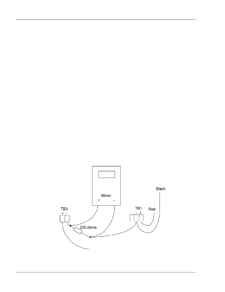
1. Remove the two position plug from TB3.
2. Remove any wires from the terminal and install a 200Ohm resistor to TB3-2. Then apply
+24V to TB3-1 and ground of the 24V supply to the other side of the resistor.
3. Reinstall the plug on TB3.
4. With the system on and no alarms present, measure the DC voltage across the resistor. A
value of 0.8VDC should register. This equates to 4mA, or normal operation.
5. Remove the water leak detection cable and wait for the unit to activate its cable trouble alarm.
Measure the DC voltage across the resistor. A value of approximately 4.0VDC should be
measured. This equates to 20mA, or a fault alarm. Reconnect the water leak detection cable.
6. Place water on the end of the water leak detection cable. Measure the DC voltage across the
resistor. The value will be proportional to the length of cable set on the dip switches. A value
of approximately 3.8V, which equates to 19mA, will be read if the length of the cable is
identical to the length set by the switches. Dry the cable.
7. Place water on the start of the cable. Measure the DC voltage across the resistor. A
measurement of approximately 1.2VDC, or 5mA, should be measured. This corresponds to a
leak at zero distance. Dry the cable.
8. Remove the resistor from the plug and reattach any wires as necessary.
Figure 4-1 4-20mA Testing