Appendix c - rsmv lcd screens, Alarm history & protected screens, Vcc-x controller technical guide 92 – Orion System VCC-X Controller User Manual
Page 92: Protected screens map, Alarm history screens
APPENDIX C - RSMV LCD SCREENS
VCC-X Controller Technical Guide
92
CONFIG
VFD TEST
ADDRESS
1(152)
REFRIG
MODULE
E-BUS
+0
SOFTWARE
1072v101
Hold for 5 seconds.
DIAGNSTC
ENTER TO
EXIT
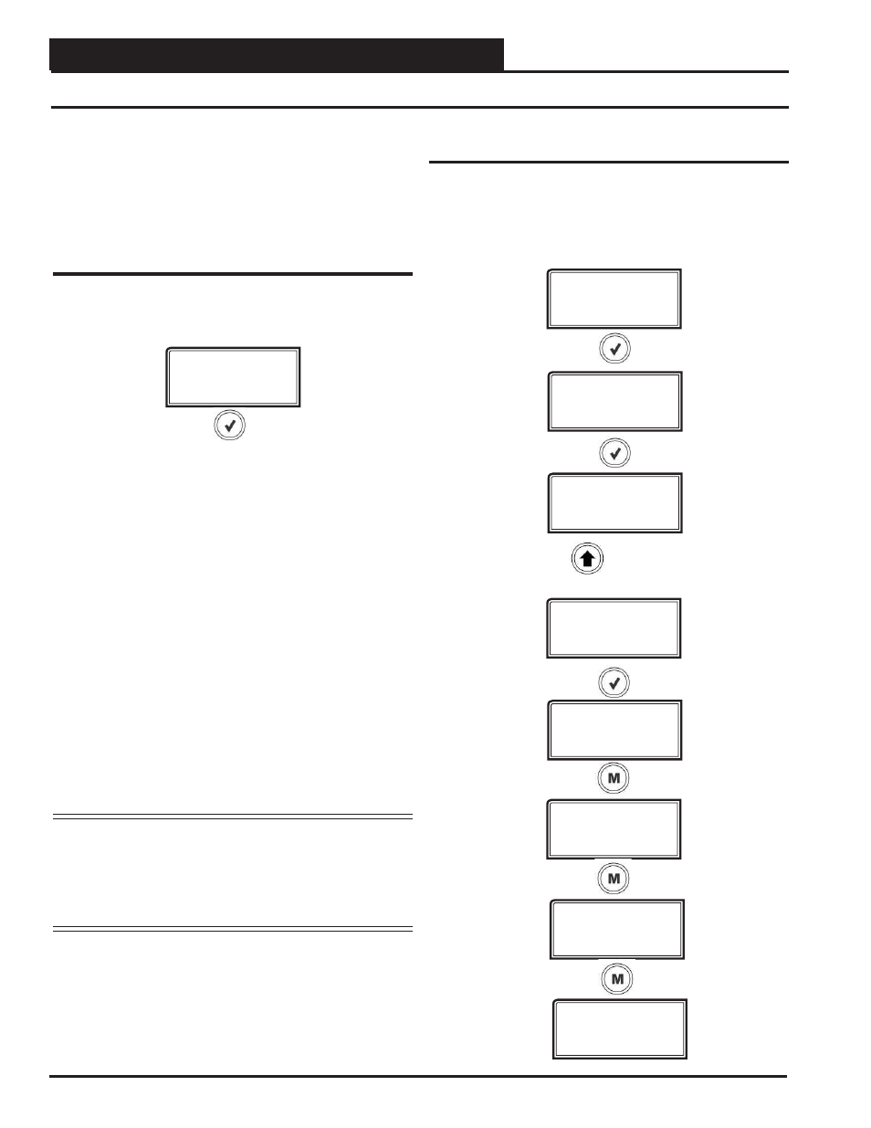
Protected Screens Map
Refer to the following map when navigating through the LCD
Protected Screens. From the REFRIG MODULE Screen, press
the
button.
Alarm History & Protected Screens
Alarm History Screens
The ALARM HISTORY Screen displays past alarms, if any, and how
long ago the last of each type occurred. From the ALARM HISTORY
Screen, press
ALARM
HISTORY
The Alarm will appear on the fi rst line and the second line will display
how long ago each alarm last occurred. As a result, the alarms listed
on the ALARMS screen will be abbreviated as follows in order of
the way they are listed in the prior ALARMS screen section.
LOW SP
—Low Suction Pressure
UNSAFE SP
—Unsafe Suction Pressure
SP SENSE
—No Suction Pressure Sensor Detected
HIGH HP
—High Head Pressure
HP SENSE
—No Head Pressure Sensor Detected
CL TEMP 1
—Coil Temp 1 Failure
CL TEMP 2
—Coil Temp 2 Failure
COMP 1 FL
—Compressor 1 Failure
COMP 2 FL
—Compressor 2 Failure
LOW SH1
—Low Superheat 1
LOW SH2
—Low Superheat 2
COMM T/0
—E-BUS Slave Timeout
NOTE:
The screen will display minutes for the fi rst 60 minutes
of alarm occurrence, hours for the next 72 hours of
alarm occurrence, and days for the next 30 days of
alarm occurrence. After 30 days, the alarm will clear.
Alarm history is not stored in memory. So, if power
is lost, the alarms will clear.
EBUS SLAVE (SLV) TIMEOUT:
This alarm indicates that com-
munication has been lost between the RSMV and the Main controller
or other E-BUS modules that may be connected. This can be the result
of a bad cable, a missing cable, or the module not being confi gured
properly.