Relay e-bus expansion module wiring, Vcc-x controller technical guide 44, E-bus 12-relay expansion module – Orion System VCC-X Controller User Manual
Page 44: Warning
12-RELAY E-BUS EXPANSION MODULE WIRING
VCC-X Controller Technical Guide
44
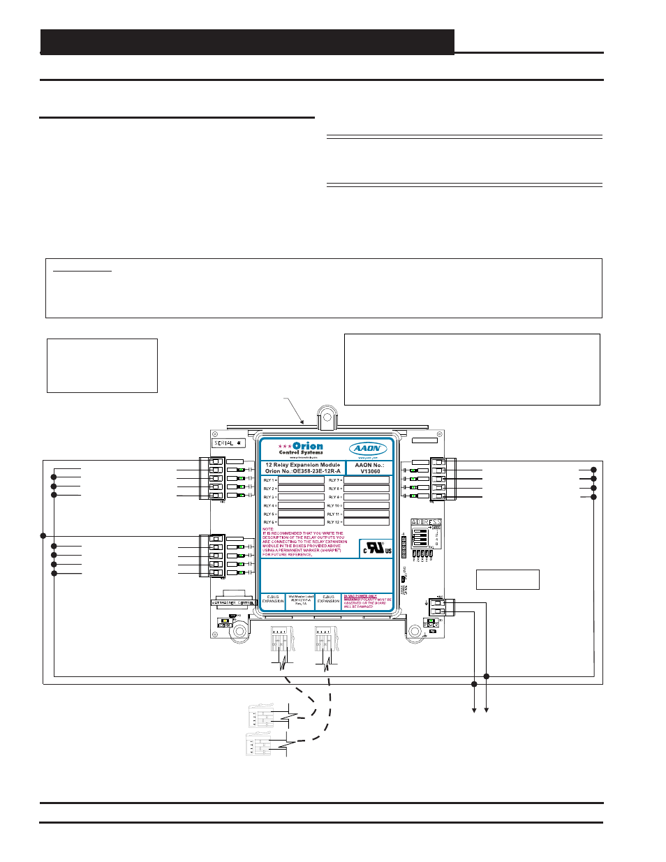
Figure 29: OE358-23E-12R-A – E-BUS 12-Relay Expansion Module Wiring
E-BUS 12-Relay Expansion Module
The E-BUS 12-Relay Expansion Module ( OE358-23E-12R-A)
provides for 12 Dry Contact Confi gurable Relay Outputs. See Figure
29 below for complete wiring details.
The E-BUS 12-Relay Expansion Module can be used in conjunction
with the VCC-X EM1 Expansion Module (OE336-23-VCCXEM1).
The expansion modules can be used individually or together to
provide the required inputs and outputs for your specifi c applications.
12-Relay E-BUS Expansion Module Wiring
E-BUS 12-Relay
Expansion Module
Configurable Relay Output #9
Configurable Relay Output #1
Configurable Relay Output #5
RLY9
R1
R5
RLY10
R2
R6
RLY11
R3
R7
RLY12
R4
R8
Configurable Relay Output #10
Configurable Relay Output #2
Configurable Relay Output #6
Configurable Relay Output #11
Configurable Relay Output #3
Configurable Relay Output #7
Configurable Relay Output #12
Configurable Relay Output #4
Configurable Relay Output #8
EBC E-BUS Cable
Connect To VCC-X Controller
EBC E-BUS Cable
Connect To Next Expansion Board
(When Used)
24 VAC
GND
15 VA Minimum
Power Required
WARNING!!
Observe Polarity! All boards must be wired with GND-to-GND and 24VAC-to-24VAC. Failure to observe polarity will result in damage to
one or more of the boards. Expansion Modules must be wired in such a way that the expansion modules and the controller are always
powered together. Loss of power to the expansion module will cause the controller to become inoperative until power is restored to the
expansion module.
NOTE:
All Relay Outputs Are
Normally Open And Rated
For 24 VAC Power Only.
1 Amp Maximum Load.
RLY9
RLY10
RLY11
RLY12
RLY-COM
MADE IN USA
RLY-COM
RLY-COM
RLY1
RLY2
RLY3
RLY4
RLY8
RLY7
RLY6
RLY5
24VAC
GND
EXPANSION BOARD
YS102324 REV 2
RELAY
24 V
A
C
GND
RLY1
RLY2
RLY3
RLY4
COM
COM
RLY5
RLY6
RLY7
RLY8
COM
NOTE: RELAY CONTACTS R1-R12 MAY BE CONFIGURED FOR:
1.) COOLING STAGES
2.) HEATING STAGES
4.) EMERGENCY HEAT
5.) MOD HEAT ENABLE
6.) MOD COOL ENABLE
7.) MORNING WARM-UP
9.)
11.) LOW AMBIENT
12.) EXHAUST
13.)
ECONOMIZER
14.)
15.) OCCUPIED
16.) OVERRIDE
10.) PREHEAT
3.) AUX HEAT
17.) ALARM
REHEAT
HEAT WHEEL
8.) MORNING COOL-DOWN
The expansion modules can be used individually or together to
provide the required inputs and outputs for your specifi c applications.
NOTE:
A total of 17 relays are available by adding the Relay
Expansion Modules. All Expansion Module relay
outputs are user-confi gurable.