Vcc-x expansion module 1 wiring, Vcc-x em1 economizer actuator feedback wiring, Vcc-x em1 expansion module – Orion System VCC-X Controller User Manual
Page 40: Vcc-x controller technical guide 40, Vcc-x em1 economizer actuator feedback, Title 24 economizer feedback
VCC-X EXPANSION MODULE 1 WIRING
VCC-X Controller Technical Guide
40
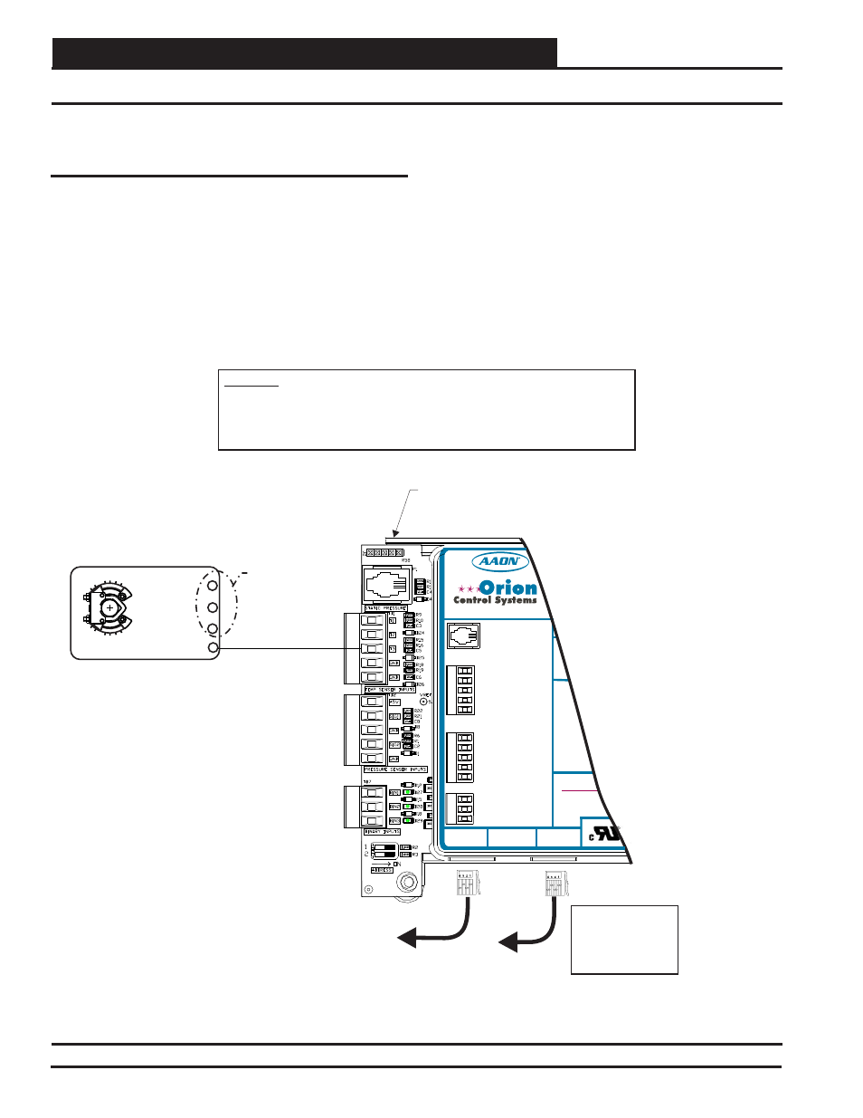
VCC-X EM1 Economizer Actuator Feedback Wiring
Figure 25: VCC-X EM1 Economizer Actuator Feedback Wiring
WARNING!!
Observe Polarity! All boards must be wired with GND-to-GND and 24VAC-to-24VAC. Failure
to observe polarity will result in damage to one or more of the boards. Expansion Modules
must be wired in such a way that the expansion modules and the controller are always
powered together. Loss of power to the expansion module will cause the controller to
become inoperative until power is restored to the expansion module.
VCC-X EM1
Expansion Module
Connect To
Expansion Module(s)
(When Used)
Connect To
Controller
VCC-X
Size Transformer
For Correct Total
Load. VCC-X E 1
Module = 5 VA
M
T3
WattMaster Label
#L102196-A
Rev.: 1A
B
A
T1
T2
ECON FEEDBACK
GND
SIG 2
+5V
BIN 1
SIG 1
BIN 2
GND
BIN 3
GND
GND
E-BUS
CONNECT
E-BUS
CONNECT
24 VAC POWE
WARNING! POL
MUST BE OBSE
THE CONTROLL
BE DAMAGED
POWER IN
BINARY INPUT TERMINALS
PRESSURE SENSOR INPUT
TERMINALS
TEMPERATURE SENSOR INPUT
TERMINALS
www.aaon.com
www.orioncontrols.com
O
NOT USED
Title 24 Economizer
Actuator Feedback
Signal 0-10VDC
(By Others)
Economizer Damper Actuator
(Belimo Actuator Shown)
Y1 3
+ 2
COM - 1
Economizer Feedback 5
Belimo Actuator Wiring
Shown. Consult Factory For
Other Manufacturer Wiring
Instructions
See Economizer
Actuator Wiring
For VCC-X
Controller
AO2
VCC-X EM1 Economizer Actuator
Feedback
The VCC-X EM1 Expansion Module (OE336-23-VCCXEM1)
connects to the VCC-X Controller with an EBC E-BUS cable and
adds an additional 5 Analog Inputs, 5 Analog Outputs, 3 Binary
Inputs, and 5 Confi gurable Relay Outputs.
The VCC-X EM1 Expansion Module can be used in conjunction with
the E-BUS 12-Relay Expansion Module. The expansion modules
can be used individually or together to provide the required inputs
and outputs for your specifi c applications.
Title 24 Economizer Feedback
If the controller has been confi gured for Title 24 Economizer
operation, the Economizer Actuator Feedback signal will be wired
to the VCC-X EM1’s T3 input.
See Figure 25 below for wiring.