Appendix d - vcc-x bacnet, Vcc-x bacnet, Parameters – Orion System VCC-X Controller User Manual
Page 102: Vcc-x controller technical guide 102
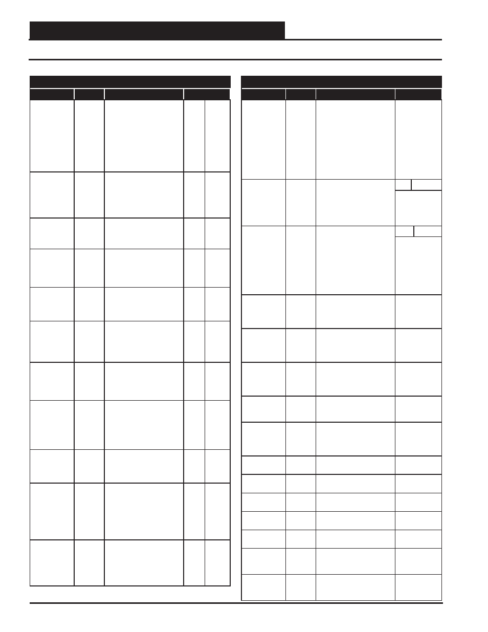
APPENDIX D - VCC-X BACnet
®
VCC-X Controller Technical Guide
102
VCC-X BACnet
®
Parameters
BACnet
®
Properties for the VCC-X Controller
Parameter
Object
Description
Limits
Indoor
Humidity
Setpoint Low
Reset Limit
AV: 53
On indoor controlled (non
MUA) units, this is the
Humidity setpoint that
initiates Dehumidifi cation.
During Coil Temp Reset,
this is the lowest Space
RH value that corresponds
to the High Coil Temp
Setpoint.
0
100
Indoor
Humidity
Setpoint High
Reset Limit
AV:54
During Coil Temp Reset,
this is the highest Space
RH value that corresponds
to the Low Coil Temp
Setpoint.
0
100
Duct Static
Pressure
Setpoint
AV:55
Current Static
Pressure Setpoint.
.10
3.0
Duct Static
Pressure
Control
Deadband
AV:56
Value above and below
the Duct Static Pressure
Setpoint where no control
change occurs.
.01
.5
Building
Pressure
Control
Setpoint
AV:57
Building
Pressure Setpoint.
-.20
.20
Building
Pressure
Control
Deadband
AV:58
Value above and below the
Building Pressure Setpoint
where no control change
occurs.
.01
.1
Minimum
Outdoor Air
CFM
AV:59
Minimum Outdoor Airfl ow
CFM Setpoint
.10K
200K
Outdoor Air
CFM
Proportional
Window
AV:60
Controls rate of change
for damper signal. As OA
CFM moves further from
setpoint within this window,
the damper makes a larger
change.
10
9999
SZ VAV Fan
Speed Integral
AV:61
The Integral Constant for
Single Zone VAV Fan
Control.
0
10
Relay Run-
time Limit
AV:62
If any confi gured relay’s run
time exceeds this number of
hours of operation, a
warning alarm is generated
so that periodic
maintenance can be
performed.
0
30000
Schedule
Force
AV: 63
0 = Auto (uses controller’s
schedule)
1 = Forced
Occupied
2 = Forced Unoccupied
0
2
BACnet
®
Properties for the VCC-X Controller
Parameter
Object
Description
Limits
HVAC Mode
Override
AV: 64
Overrides normal controller
operation in order to force
the unit into this desired
mode. Confi guring for
“Auto” will restore normal
unit control of the mode of
operation.
0=Auto
1=Vent
2=Cool
3=Heat
4=Vent
Dehum.
5=Cool
Dehum.
6=Heat
Dehum.
Fan VFD
Override
AV: 65
Override to force the VFD
to this percentage speed.
Confi guring “Auto” will
restore normal unit control
of the VFD speed.
0%
100%
Auto=65535
Outdoor Air
Damper
Override
AV: 66
Overrides all other Outdoor
Air Damper position
commands so as to maintain
this fi xed position.
Confi guring for “Auto” will
restore normal unit control
of the Outdoor Air Damper/
Economizer operation.
0%
100%
Auto=65535
Cooling
Enabled
Status
BI: 1
Status that indicates
Mechanical Cooling is
enabled based on the
Cooling Lockout.
Heating
Enabled
Status
BI: 2
Status that indicates that
Mechanical Heating is
enabled based on the
Heating Lockout.
Economizer
Enabled
Status
BI: 3
Status that indicates
the Economizer is enabled
based on the Economizer
Enable Setpoint.
Reheat
Enabled
Status
BI:4
Modulating Hotgas Reheat
Enabled.
Emergency
Heat Enabled
Status
BI:5
Shows the Emergency
Heat is enabled based on
the Compressor Heating
Lockout.
Proof of
Airfl ow
BI:6
Proof of Airfl ow Binary
Input Status
Exhaust Hood
On/Off Status
BI:7
Exhaust Hood On/Off
Binary Input Status
Remote Force
Occupied
BI:8
Remote Forced Occupied
Mode Binary Input Status
Remote Force
Cooling
BI:9
Remote Forced Cooling
Mode Binary Input Status
Remote Force
Heating
BI:10
Remote Forced Heating
Mode Binary Input Status
Remote Force
Dehumidifi ca-
tion
BI:11
Remote Force
Dehumidifi cation Mode
Binary Input Status
Bad Supply
Air Sensor
BI: 12
Alarm that indicates a
failure of the Supply Air
Sensor.