Preheat-x controller wiring, Vcc-x controller technical guide 48, Leaving air temperature setpoint – Orion System VCC-X Controller User Manual
Page 48: Entering air temperature setpoint, Preheat enable signal, Leaving air temperature status, Entering air temperature status, Alarm status
PREHEAT-X CONTROLLER WIRING
VCC-X Controller Technical Guide
48
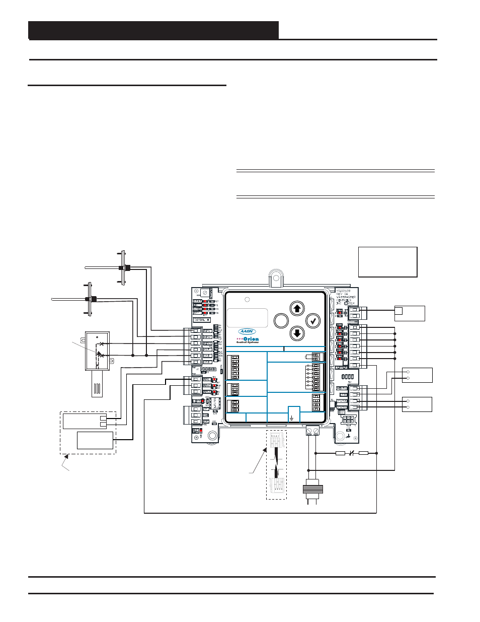
PREHEAT-X Controller Wiring
Figure 33: PREHEAT-X Controller to VCC-X Controller Wiring
M
ENTER
UP
DOWN
ALARM
MENU
ALARM CONTACT
HEAT 1
HEAT 2
HEAT 3
HEAT 4
HEAT 5
HEAT 6
RLY COMM
HEAT
OUTPUTS
ANALOG
OUTPUTS
0-10V MOD. SCR
GND
PWM +
PWM -
OE377-26-00061 PREHEAT-X
AAON No.: V48510
WattMaster Label
#LB102XXX-A
Rev.: 1A
E-BUS
CONNECT
E-BUS
CONNECT
LAT1
0-10V RESET
LAT2
OAT
GND
GND
ANALOG INPUTS
BINARY INPUTS
RS-485 COMM
+24
V
AC
GND
www.orioncontrols.com
www.aaon.com
ENABLE
T(-)
EMERG. SHUTDOWN
SHLD
FUTURE USE
R(+)
CONTACT RATING IS
1 AMP MAX
@ 24 VAC
AIN1
Entering Air Temperature
Sensor
Reset In
0-10 VDC
GND
+
-
Emergency
Shutdown
Line
GND
24V
AC
40 VA
Transformer
Minimum
Heat 1 Relay
Heat 2 Relay
Heat 3 Relay
Heat 4 Relay
Heat 5 Relay
Heat 6 Relay
COM
Alarm
Note:
All Relay Outputs Are
Normally Open And Rated
For 24 VAC Power Only.
1 Amp Maximum Load.
Relay
Contact
–
PWM SSR
+
–
Modulating SCR
(0-10 VDC)
+
PREHEAT-X CONTROLLER
(OE377-26-00061)
AIN2
AIN3
RST
GND
GND
BIN1
BIN2
Leaving Air 2
Temperature Sensor
Leaving Air 1
Temperature Sensor
SAFETIES
(BY OTHERS)
N.C.
Heat Enable
Signal (24 VAC)
W1
NOTE: Reset In And Heat
Enable Inputs Are Used In
Stand-Alone Mode Only
Mount Inside PREHEAT-X
Box Wall
Make Splice
Connections
Inside Sensor
Enclosure
As Shown. Seal All
Conduit Fittings With
Silicone Sealant
Mount Sensor Outdoors
In Shaded Protected
Area & In Upright
Position As Shown
Mount Inside PREHEAT-X
Box Wall
M
ENTER
UP
DOWN
ALARM
MENU
ALARM CONTACT
HEAT 1
HEAT 2
HEAT 3
HEAT 4
HEAT 5
HEAT 6
RLY COMM
HEAT
OUTPUTS
ANALOG
OUTPUTS
0-10V MOD. SCR
GND
PWM +
PWM -
OE377-26-00061 PREHEAT-X
AAON No.: V48510
WattMaster Label
Rev.: 1D
#S
000062
W
E-BUS
CONNECT
E-BUS
CONNECT
LAT1
0-10V RESET
LAT2
EAT
GND
GND
ANALOG INPUTS
BINARY INPUTS
RS-485 COMM
+24 V
A
C
GND
www.aaon.com
ENABLE
T(-)
EMERG. SHUTDOWN
SHLD
FUTURE USE
R(+)
CONTACT RATING IS
1 AMP MAX
@ 24 VAC
www.orioncontrols.com
MSTP
BACnet
EBC E-BUS Cable
Connects To
VCC-X Controller’s
Expansion Port
PREHEAT-X Controller Wiring
The OE377-26-00061 PREHEAT-X Controller (AAON Part No.
V48510) is designed to control fi xed stages of Preheat and optional
modulating Preheat to maintain a desired Preheat Leaving Air
Temperature Setpoint. The PREHEAT-X Controller directly connects
to the VCC-X Controller or indirectly using an E-BUS Expansion
Board via an EBC E-BUS cable. See Figure 33 for wiring.
The following information will be passed between the PREHEAT-X
Controller and the VCC-X Controller:
Leaving Air Temperature Setpoint
Entering Air Temperature Setpoint
Preheat Enable Signal
Leaving Air Temperature Status
Entering Air Temperature Status
Alarm Status
If the communication is interrupted between the
PREHEAT-X Controller and the VCC-X Controller,
the PREHEAT-X controller will be disabled.
For more information, refer to the PREHEAT-X Controller Technical
Guide.
NOTE:
If using multiple E-BUS Sensors or Modules, the
E-BUS Hub or Adapter Board may be required.