Vcc-x expansion module 1 wiring, Chilled water valve actuator wiring, Vcc-x em1 expansion module – Orion System VCC-X Controller User Manual
Page 42: Vcc-x controller technical guide 42, Modulating cooling output, Line voltage
VCC-X EXPANSION MODULE 1 WIRING
VCC-X Controller Technical Guide
42
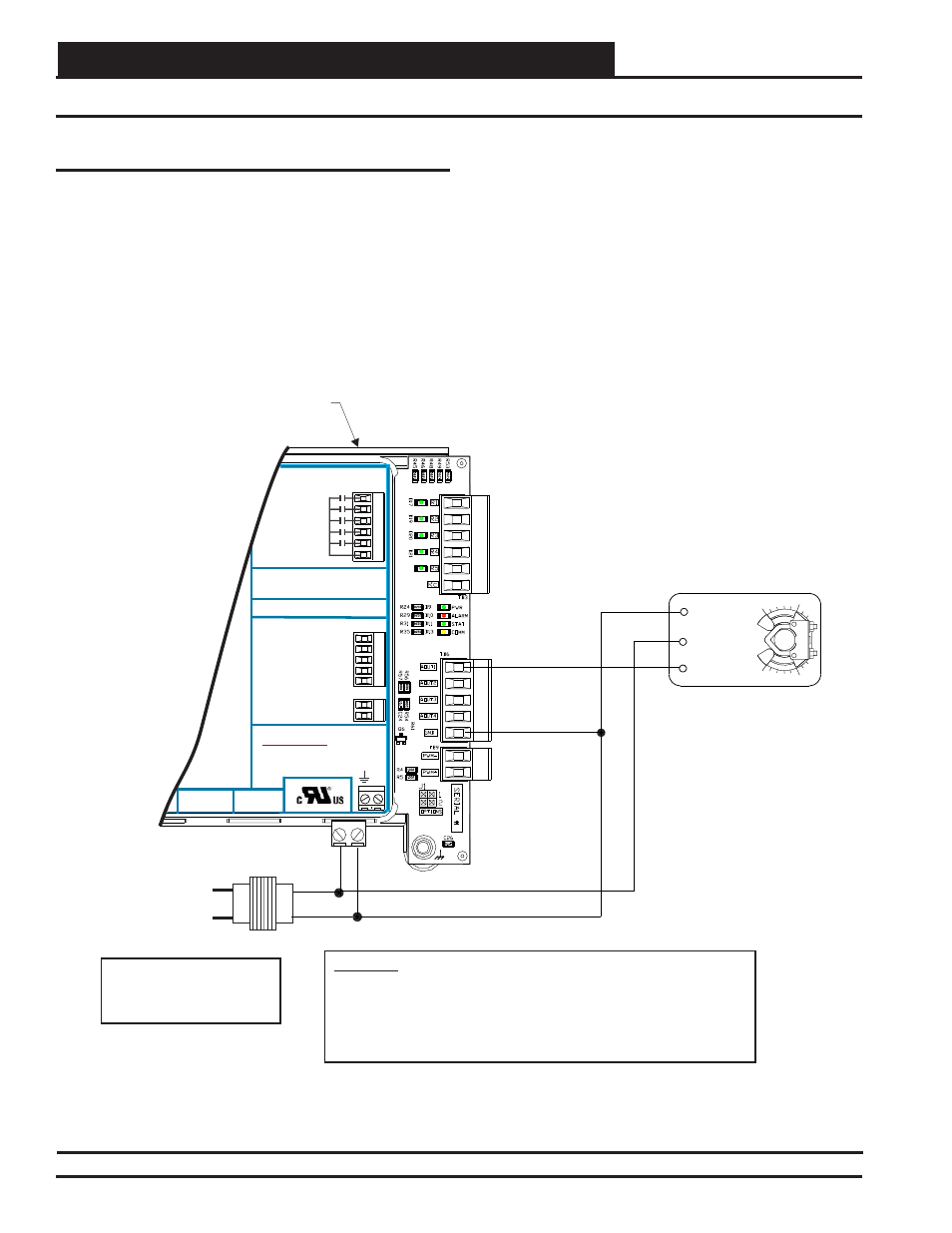
Chilled Water Valve Actuator Wiring
Figure 27: Chilled Water Valve Actuator Wiring Diagram
Modulating Cooling Output
This output is used to control a Modulating Chilled Water Valve to
maintain the Cooling Supply Air Temperature Setpoint. The output
is confi gured for either 0-10 VDC or 2-10 VDC operation and can be
confi gured for direct acting or reverse acting operation. See Figure
27 for wiring details.
CHILLED WATER VALVE
ACTUATOR
2 +
Y1
3
COM
1
VCC-X EM1
Expansion Module
WARNING!!
Observe Polarity! All boards must be wired with GND-to-GND and 24VAC-to-
24VAC. Failure to observe polarity will result in damage to one or more of the
boards. Expansion Modules must be wired in such a way that the expansion
modules and the controller are always powered together. Loss of power to the
expansion module will cause the controller to become inoperative until power is
restored to the expansion module.
AOUT1
24VAC
GND
Line Voltage
Size Transformer For
Correct Total Load.
VCC-X E 1 Module = 5 VA
M
GND
WattMaster Label
#L102196-A
Rev.: 1A
B
+24
VAC
GND
RELA
Y
C
ONT
A
CT
RA
TING
IS
1
A
MP
MAX
@
24
V
A
C
R1
R2
R3
R4
R5
RC
RELAY OUTPUT
TERMINALS
ANALOG OUTPUT TERMINALS
GND
RETURN DAMPER
RETURN BYPASS
CHILLED WATER
AOUT4
PWM –
PWM +
E-BUS
CONNECT
24 VAC POWER ONLY
WARNING! POLARITY
MUST BE OBSERVED OR
THE CONTROLLER WILL
BE DAMAGED
POWER INPUT TERMINAL BLOCK
PUT
T
VCC-X Expansion Module 1
Orion No.: OE336-23-VCCXEM1
AAON No.: V53990