Gasboy Atlas Commercial Series User Manual
Page 41
PT-1949D Gasboy Atlas™ Pump and Dispenser Illustrated Parts Manual · March 2010
Page 35
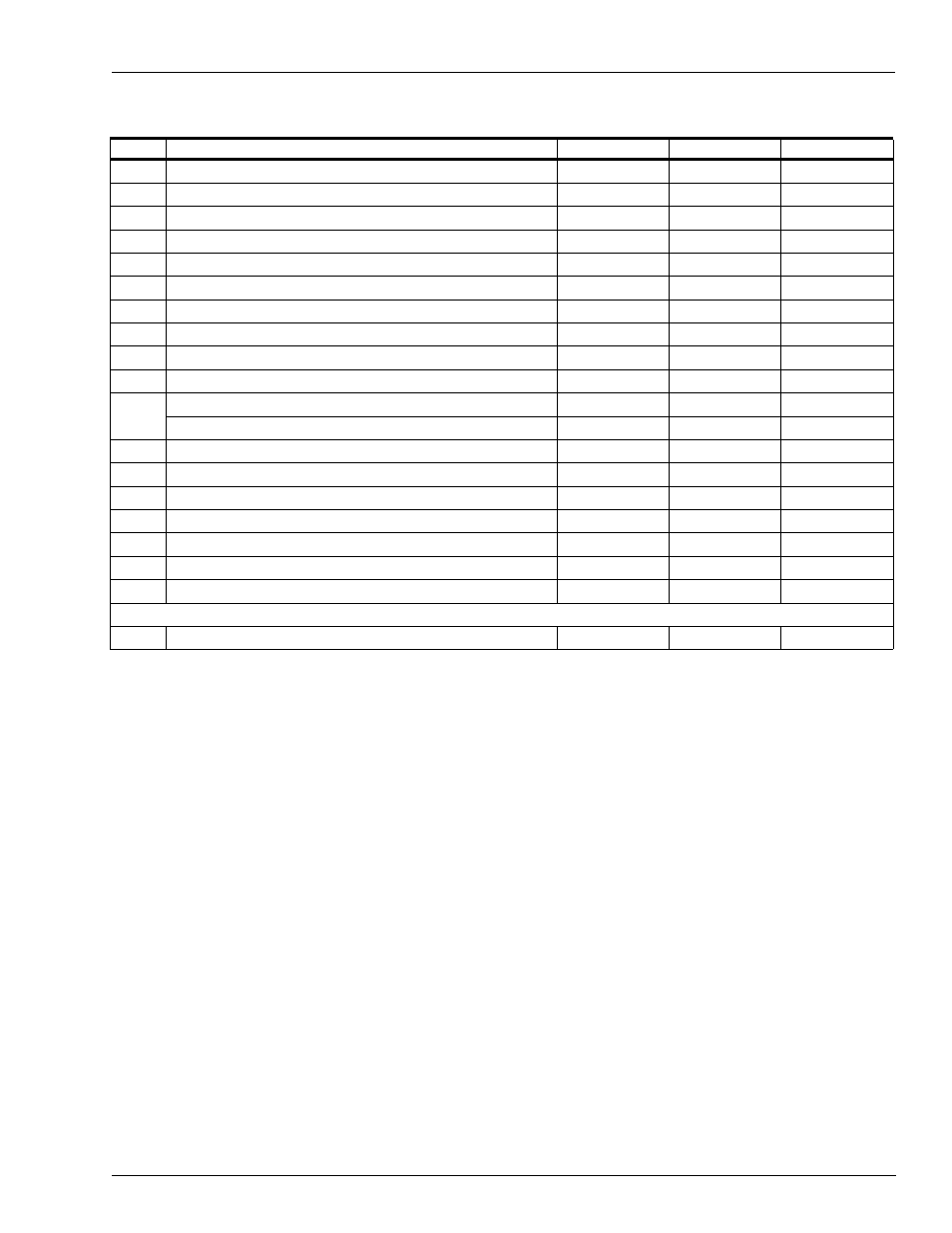
Lower Hydraulics - Self-contained
Hydraulic Area Section
Note:
Item #
Part Description
Current Part
Previous Part
Quantity
1
O-Ring 2.37 X 0.103
Q10067-31
-
1
2
Adaptor - EP2 Inlet
023146
-
1
3
Lock Washer Metric M10 Zinc Plate
M01071B001
-
3
4
Socket Head Cap Screw, M10 X 25
M04973B005
-
3
5
Screw Metric M8 X 16
M00415B009
-
8
6
Ferule Compression
K43260
-
2
7
Nut, Compression Fitting
Q12505-01
-
2
8
Finished Hex Check Nuts
Q10985-02
-
1
9
Tube, Sump Vent
M07391B001
M04754B001
1
10
Fitting, Sump Vent
N21861-02
-
1
11
Feedline Assembly Single 1 Grade
M04830A001
-
1
Feedline Assembly Dual 1 Grade
M04831A001
-
1 per unit
12
O-Ring 1.149 X 0.139
Q10068-07
-
1
13
Pump Discharge Flange
M04686B001
-
1
14
Socket Head Cap Screw, M6 X 26
M04973B001
-
2
15
O-Ring 1.234 X 0.139
Q10068-09
-
1
16
Grommet, Discharge 1 In, Pipe
028960
-
1
17
Elbow 1 In, X 50º, Painted
024895
-
1
18
GPU Pumping Unit
M04920B003
M04920B001
1
Not Shown
19
V-Belt 4L290
R06711-52
-
1
Quantities are in per grade.
Note: For motor and conduit, refer to
“Self-contained Motors - 8700, 8800, 9100, 9840,
on