B.4 redundant system configuration, B.4.1.1 initial configuration, Redundancy-config?-on--- -converter-#-bu :03 – Comtech EF Data DT-4500-A Series User Manual
Page 148: Redundancy-config?-on--- -converter-#-01----pol-1, Redundancy-config?-on--- -converter-#-02----pol-1, Redundancy-config?-on--- -converter-#-03----pol-1
DT-4500-A Series Downconverters
Revision 0
Appendix B
MN-DT4500A
B–8
B.4 Redundant System Configuration
B.4.1 Redundant System Configuration Using the Front Panel
Chapter 5. FRONT PANEL OPERATION
B.4.1.1
Initial Configuration
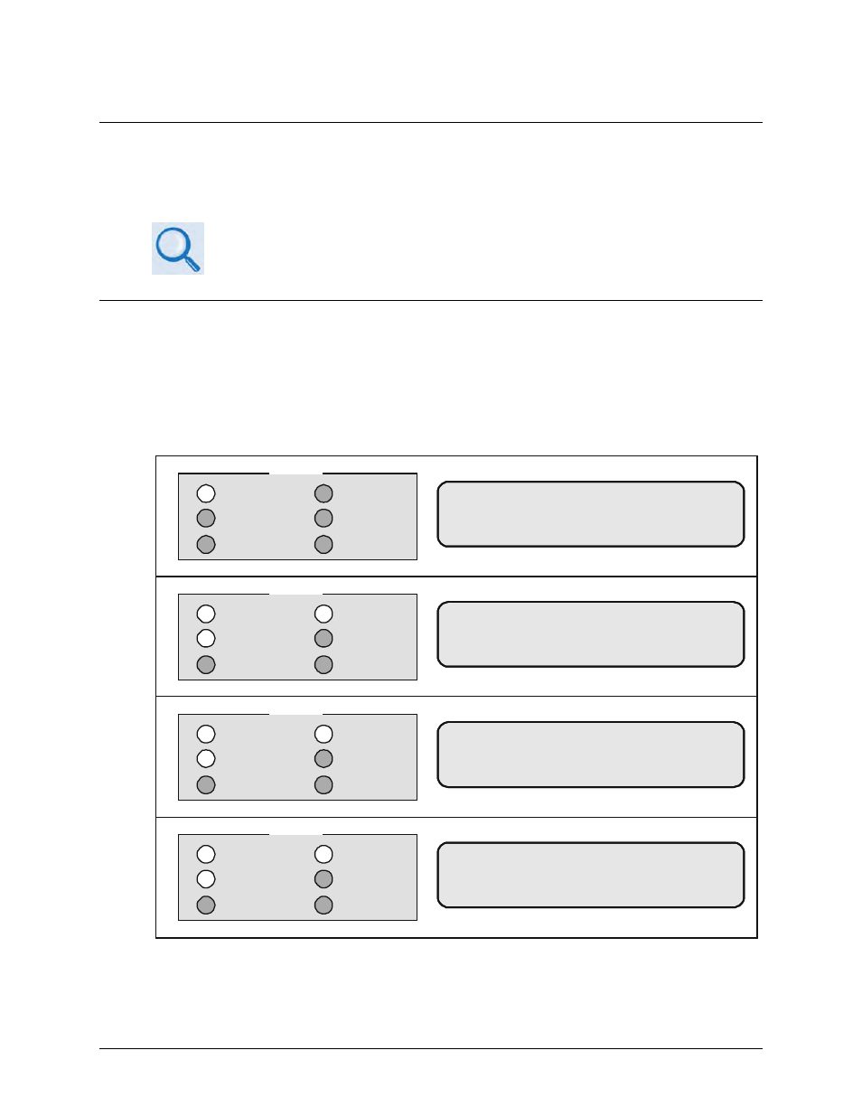
Redundant system configuration is controlled from the downconverter’s front panel
configuration menu. Each online unit is assigned a redundancy configuration address. This
address is dependent on the location of the online downconverter with reference to the backup.
The unit closest to the backup must be Downconverter # 1. The next unit down must be
Downconverter # 2. Figure B-9 shows the appropriate entries for a 1:3 system.
REDUNDANCY-CONFIG?-ON---
-CONVERTER-#-BU---1:03--
POWER ON
TRANSMIT
REMOTE
ON LINE
FAULT
STORED FAULT
STATUS
REDUNDANCY-CONFIG?-ON---
-CONVERTER-#-01----POL-1
POWER ON
TRANSMIT
REMOTE
ON LINE
FAULT
STORED FAULT
STATUS
REDUNDANCY-CONFIG?-ON---
-CONVERTER-#-02----POL-1
POWER ON
TRANSMIT
REMOTE
ON LINE
FAULT
STORED FAULT
STATUS
REDUNDANCY-CONFIG?-ON---
-CONVERTER-#-03----POL-1
POWER ON
TRANSMIT
REMOTE
ON LINE
FAULT
STORED FAULT
STATUS
Figure B-9. Front Panel Displays
Configure the online units first, and then configure the backup unit. Redundant polling starts
when the backup is configured. If this polling starts before the online units are configured, a