A.7.3 modes, A.7.3.1 redundant mode – Comtech EF Data DT-4500-A Series User Manual
Page 129
DT-4500-A Series Downconverters
Revision 1
Appendix A
MN-DT4500A
A–19
A.7.3 Modes
There are two modes of operation that may intersect: Redundant Mode and Automatic Mode.
A.7.3.1 Redundant Mode
Since the default mode is OFF, each converter including the backup converter must be
commanded into the Redundant Mode.
Polling on the high speed bus will not begin until the position assignments are made.
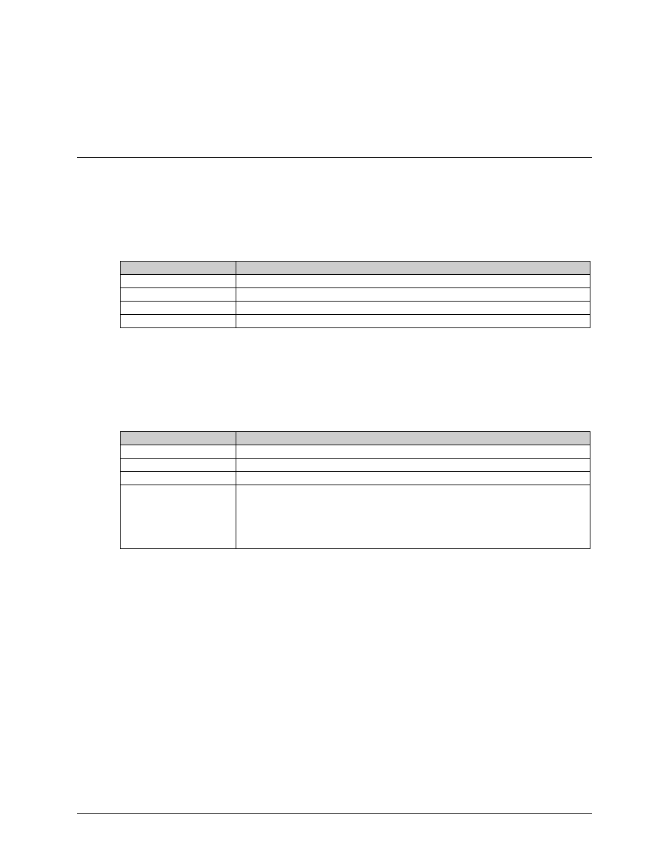
Command
Details
Redundant Mode:
Confirmation: >DEV/RED_xxx'cr''lf'] Redundant Status: Confirmation: >DEV/RED_xxx'cr''lf'] Note: The primary units must all be configured properly in redundant mode before redundant mode is enabled on the backup unit. Each converter's chain position must be initialized including the backup converter. The following redundancy initialization command is only allowed if Redundancy Mode has been selected. Command Details Initialize Command: Confirmation: >DEV/ICT_xx_yy'cr''lf'] Initialize Status: Confirmation: >DEV/ICT_xx_yy'cr''lf'] xx = chain position = 01 to 12, or BU. Where BUselects the converter as the backup. yy = chain length for xx = BU (i.e. Backup converter) 01 to 12. yy = unused if xx = 01 to 12 (i.e. chain converter) Example 1: The following command assigns the converter chain position "1". >DEV/ICT_01'cr''lf'] Example 2: The following command assigns the receiving converter as the backup converter in a 1:8 system. >DEV/ICT_BU_08'cr''lf'] Important: It should be reiterated that only the converter physically located at the top of a redundant rack should be assigned as the Backup unit. Likewise, assignment of chain positions in a redundant rack should be made according to the physical allocation of each converter in the rack (i.e. The top converter should be the Backup, the second converter should be assigned chain position 1, the third converter position 2, etc.).