ATEIS UAPg2 User Manual
Page 62
UAPG2 MANUAL
Version EN.24
62
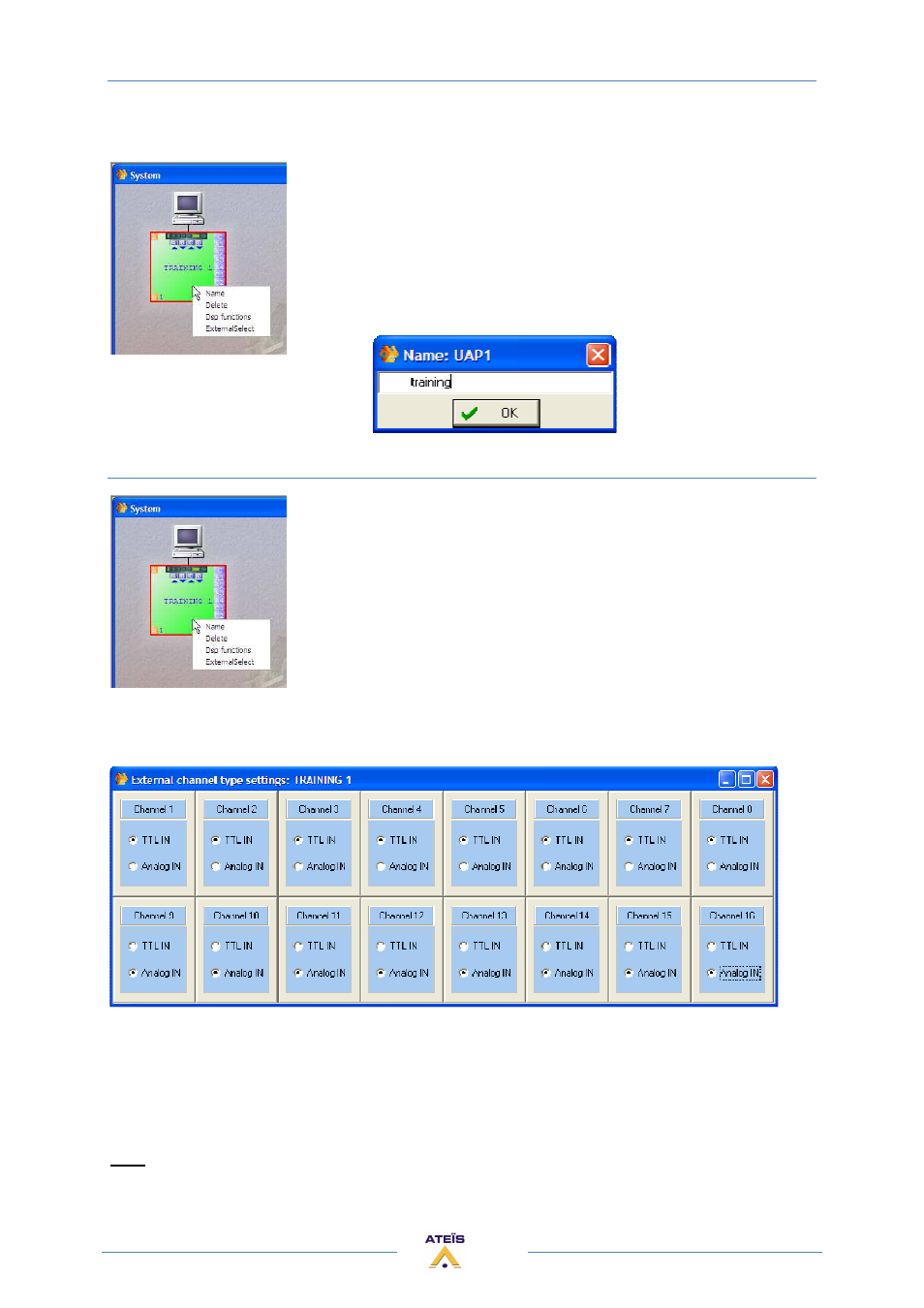
If you right click on the dragged and dropped UAPG2 icon you will have access to some features:
•
Name: give a name to this UAPG2
•
Delete: same issue as selecting and press “DEL” key (delete the
virtual UAPG2)
•
Dsp functions: same effect as double-clicking on the UAPG2 icon,
open the dsp design working area (see create audio signal path)
•
ExternalSelect: define the kind of each control input (Logic in (TTL)
or analogue in)
Name
3) Define control inputs as TTL (logic) or Analogue Inputs
Simply right-click on the desired virtual UAPG2 and select ExternalSelect
option and choose which input is what.
Caution, in order all TTL IN must be before the Analogue. You cannot
mix them freely.
ExternalSelect :
The TTL inputs work by groups. In the Logic IN window, you have to assign each TTL input to a group.
By default only the TTL inputs from 1 to 8 are already assigned to group 1 to 8.
If you set the others channel ( 9 to 16 ) in TTL IN mode, than you have to configure the groups 9 to
16 in the Logic IN window (that means assign TTLin 9 to group 9, and TTLin 10 to group 10, etc).
Note: An analogue input can control a component's parameter only if his corresponding
component's input and output are linked to something in the design.