ATEIS UAPg2 User Manual
Page 20
UAPG2 MANUAL
Version EN.24
20
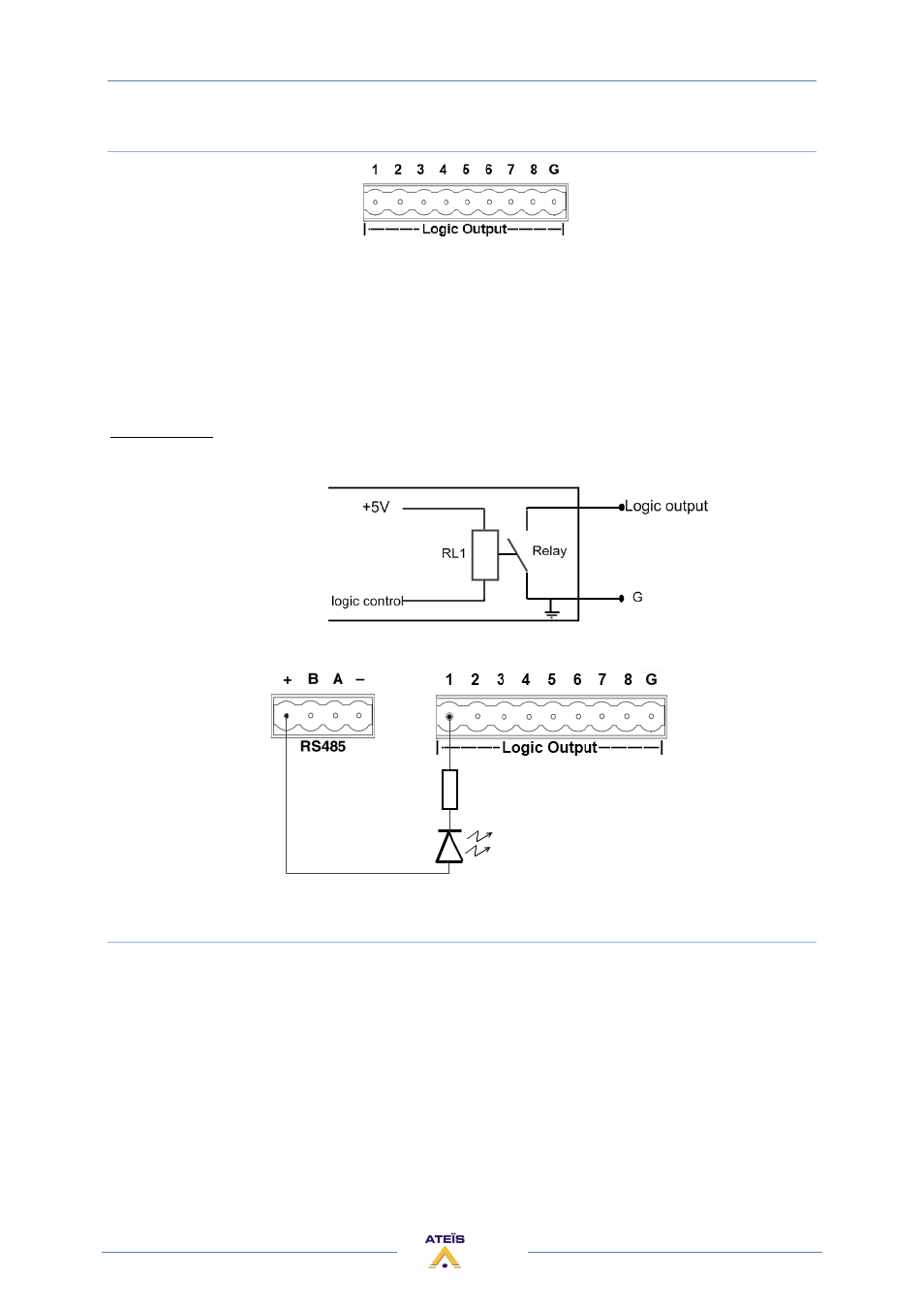
9) LOGIC OUTPUTS CONNECTORS
The Contact closes when the Logic Output is active.
The logic outputs are simple dry contact or relay contact, with a common rail.
The common rail is linked to the ground.
Caution: Do not connect voltage (24V) to the common rail.
No voltage is provided.
Contact rating: (relays EGE type EDR201A0500)
Maximum voltage 100 VDC, Maximum switching current 0.5 amps, Maximum switching power 10VA
If the RS485 bus is unused, then you can easily use the 24V DC output of the LAPG2 to feed 8 LEDS
that each have a 2k2 current limiting resistor.
10) AUDIO INPUT/OUTPUT CONNECTOR
Balanced Audio input or output:
•
S = Shield
•
+ = Hot audio signal
•
- = Cold audio signal
Input and output cards have different connector colours:
•
BLACK = OUTPUT
•
GREEN = INPUT
If you want to use unbalanced signal please connect the Cold (-) pin with the Shield (S) pin.
There is a hardware clip operation on input board over 15dBu.