ATEIS UAPg2 User Manual
Page 131
UAPG2 MANUAL
Version EN.24
131
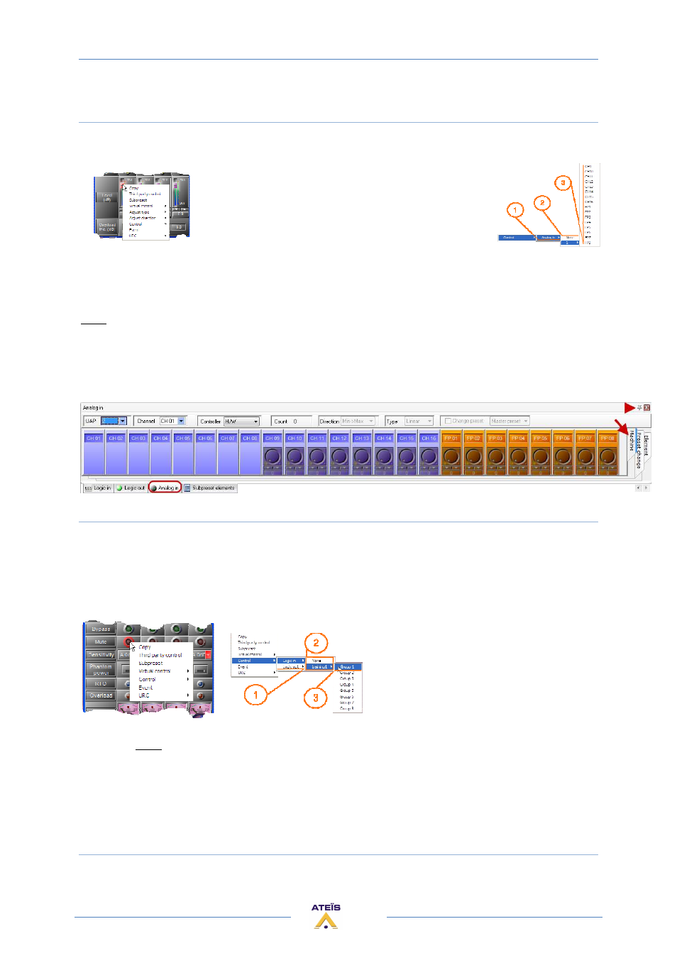
Analogue Inputs
Second step right click on the software adjustments you want to pilot with the control input and
choose control option:
1) Type of control you can assign to this software control (adjustments)
2) Name of the UAPG2 in the system
3) Connector channel number (FP = front panel knob)
Note : An analogue input can control a component's parameter only if his corresponding
component's input and output are linked to something in the design.
Don't forget to calibrate your external "variator resistance": Tools/VR calibration
The "Machine" tab of the Analogue IN floating window able to check the analogue input.
Logic inputs
The analogue/logic input must be set as TTL IN in the external settings.
Each used TTL IN must be assigned to a group to be available (Logic IN floating window).
Second step right click on the software adjustments you want to pilot with the control input and
choose control option:
1)
Type of control you can assign to
this software control (adjustments)
2)
Name of the UAPG2 in the system
3)
Connector channel number (FP =
front panel knob)
When you open the hardware contact this will active the selected software button.
If you want to active a parameter when the contact closes, then you have to use the event
Management (in menu View), to create "Element control" event. Then you can assign this event
either to an opened or closed contact.