Dataman 40Pro User Manual
Page 22
22
Notes: When LED OK or LED ERROR ON (shine), this status is presented as logical H, level
of H is 1,8V - 5V depend on H level of desired ISP device.
When LED OK or LED ERROR OFF (not shine), this status is presented as logical L, level of
L is 0V - 0,4V.
The above mentioned values are provided to understand (and also to exactly calculate) the
value of resistors, which isolate (separate) the programmed chip and target system.
Specification of ISP connector pins depends on the device, which you want to program. You
can find it in the control SW for programmer (PG4UW), menu Device / Device Info (Ctrl+F1).
Be aware, the ISP programming way of respective device must be selected. It is indicated by
(ISP) suffix after name of selected device.
These specifications correspond with application notes published of device manufacturers.
Note: Pin no. 1 is signed by triangle scratch on ISP cable connectors.
As ISP connectors are used 20 pins connectors 09185207813 from Harting or other
compatible connector.
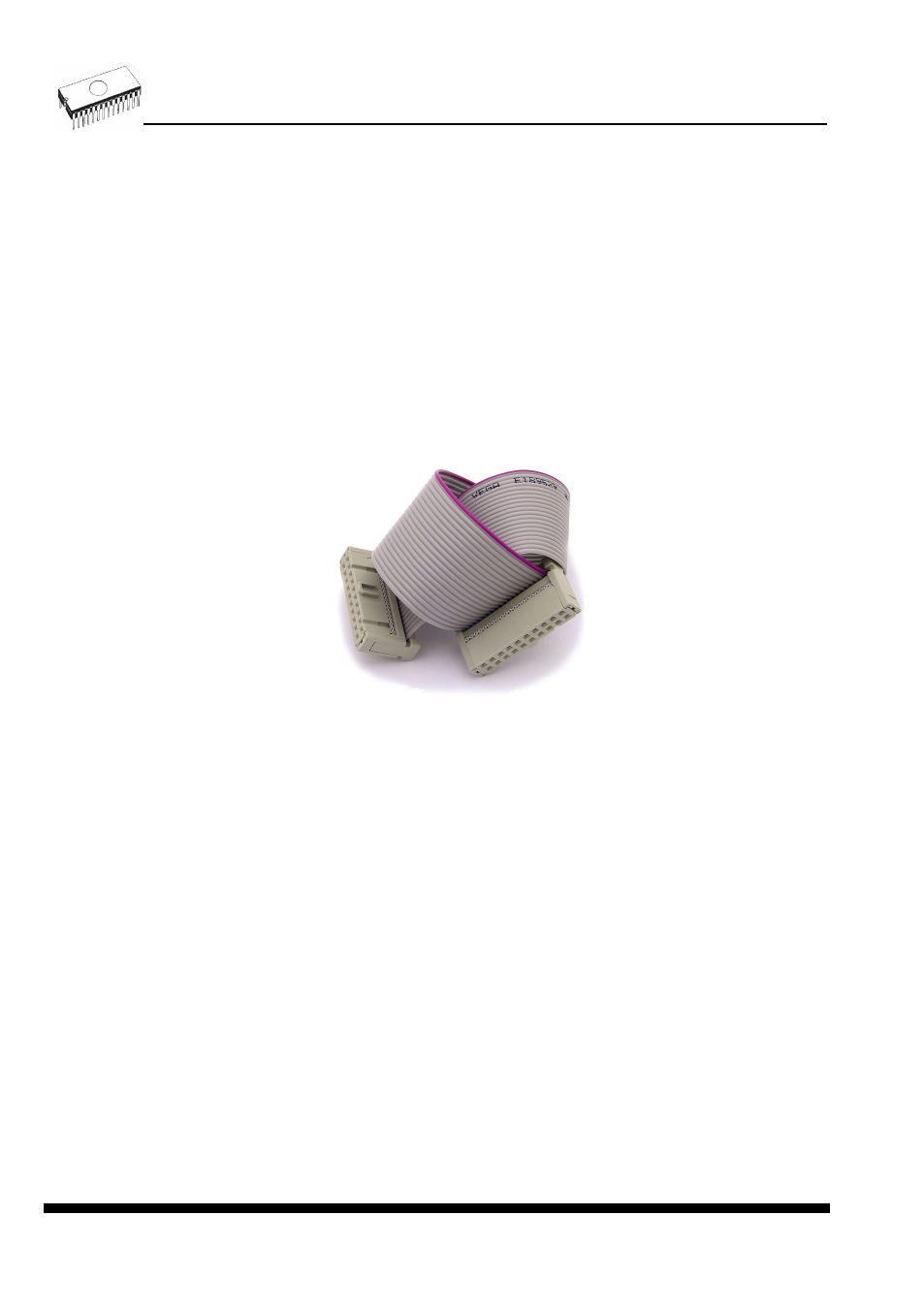
DATAMAN-448PRO2 ISP cable
Warnings:
Use only attached ISP cable. When you use other ISP cable (other material, length…),
programming may occur unreliable.
DATAMAN-448PRO2 can supply programmed device (pin 1 of ISP connector) and
target system (pins 19 and 20 of ISP connector) with limitation (see Technical
specification / ISP connector).
DATAMAN-448PRO2 apply programming voltage to target device and checks his value
(target system can modify programming voltage). If the programming voltage is different
as expected, no action with target device will be executed.