3 installation methods, 1 procedure – CIRCUTOR CVMk2 Series User Manual
Page 16
16
CVM
k2
INTRODUCTION
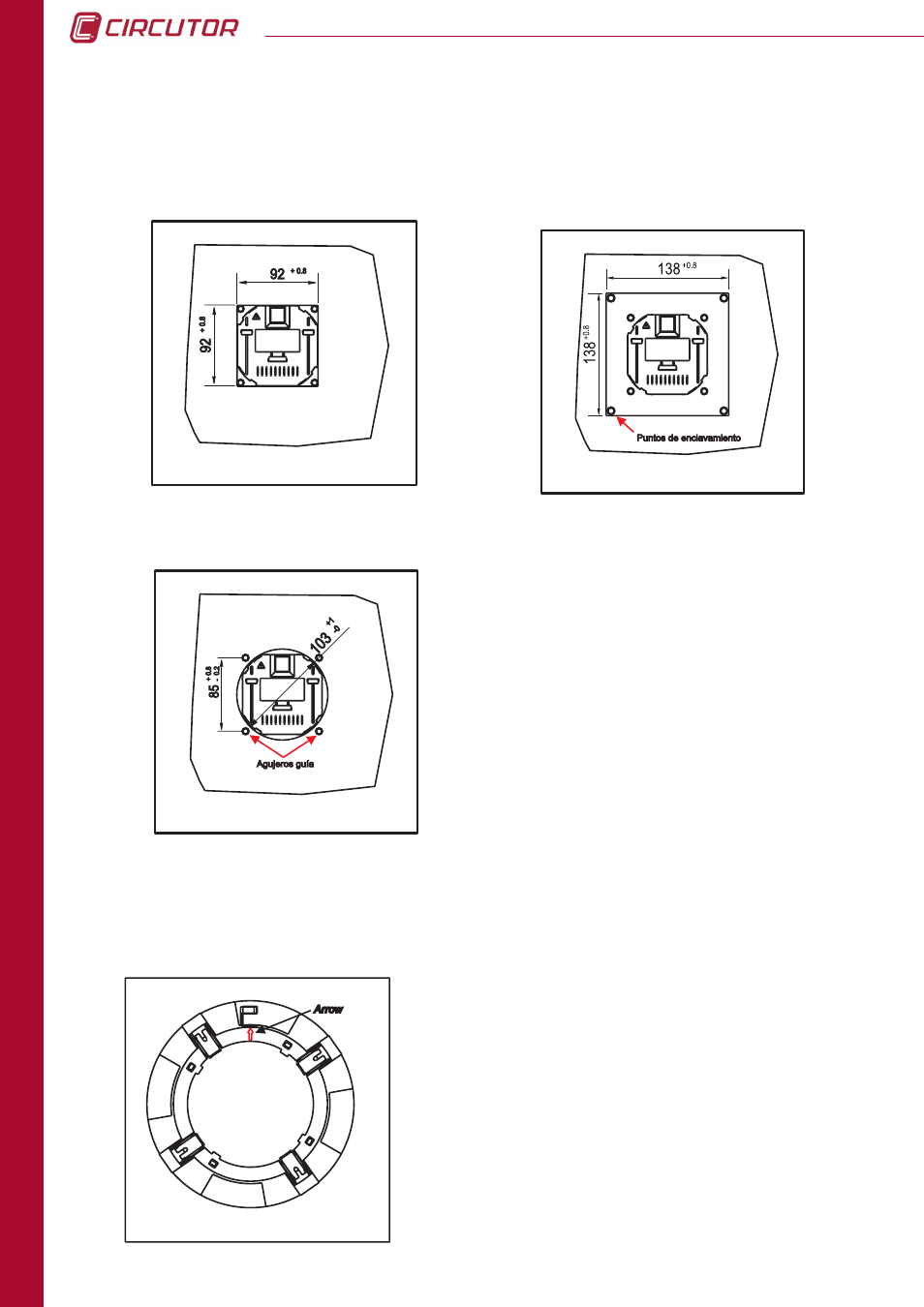
2.3 INSTALLATION METHODS
The figures illustrate how to mount the front part
(display) in a 92x92 mm (3,62 x 3,62 in) hole, a 103
mm (4,06 in) diameter hole and in a 138x138 mm (
5,43 in) hole.
After inserting the front part, install the mount ring,
making sure that the tabs are not blocked (see
procedure). Also, assure that the white arrow, which
indicates the point where the communications cable
and the RJ-45 display screen power supply cable
run out, lines up with the arrow on the measuring
equipment.
2.3.1 PROCEDURE
The tabs are components used to fasten the system to
the panel. When mounting the system, the tabs must be
free, and unblocked, so that as pressure is applied to
the mount ring the tabs go over the clamp zipper teeth.
Similarly, to dismount the panel display the tabs should
be blocked, i.e. opened prior to dismounting.
The figures illustrate the different installation possibilities, permitted by the display screen
design. The system design facilitates screwing the panel on (92
+0.8
+ 92
+0.8
mm, 138
+0.8
+ 138
+0.8
mm and a 103 mm diameter hole).