3 unbalance and asymmetry – CIRCUTOR CVMk2 Series User Manual
Page 121
121
CVM
k2
QUALITY
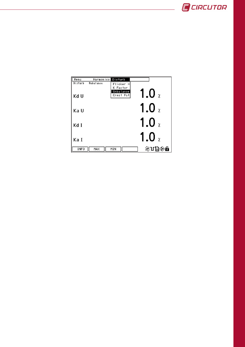
7.2.3 UNBALANCE AND ASYMMETRY
Imbalance is calculated by applying the Fortescue and Stokvis symmetric components method.
These values represent how imbalanced the facility is and the correct connection of the
phases.
These values are displayed on the screen as a %. The following variables are displayed on
the screen.
On this screen, the following options are shown above the function buttons:
Info
: This displays the system information screen (Section 6.1.1.1., System Information).
Max
: This displays the screen with the maximum values stored. The maximum values for each
variable recorded since the last reset are displayed on the screen along with the date
and time of registry.
On the
Max
screen, the
INST.
option appears, which can be used to return to the screen
that displays the instantaneous variables.
Min
: This displays the screen with the minimum values stored. The minimum values for each
variable recorded since the last reset are displayed on the screen along with the date
and time of registry.
On the
Min
screen, the
INST.
option appears, which can be used to return to the screen
that displays the instantaneous variables.
k
d
U
: Voltage imbalance coefficient.
k
a
U
: Voltage asymmetry coefficient.
k
d
I
: Current imbalance coefficient.
k
a
I
: Current asymmetry coefficient.