Altera JNEye User Manual
Page 187
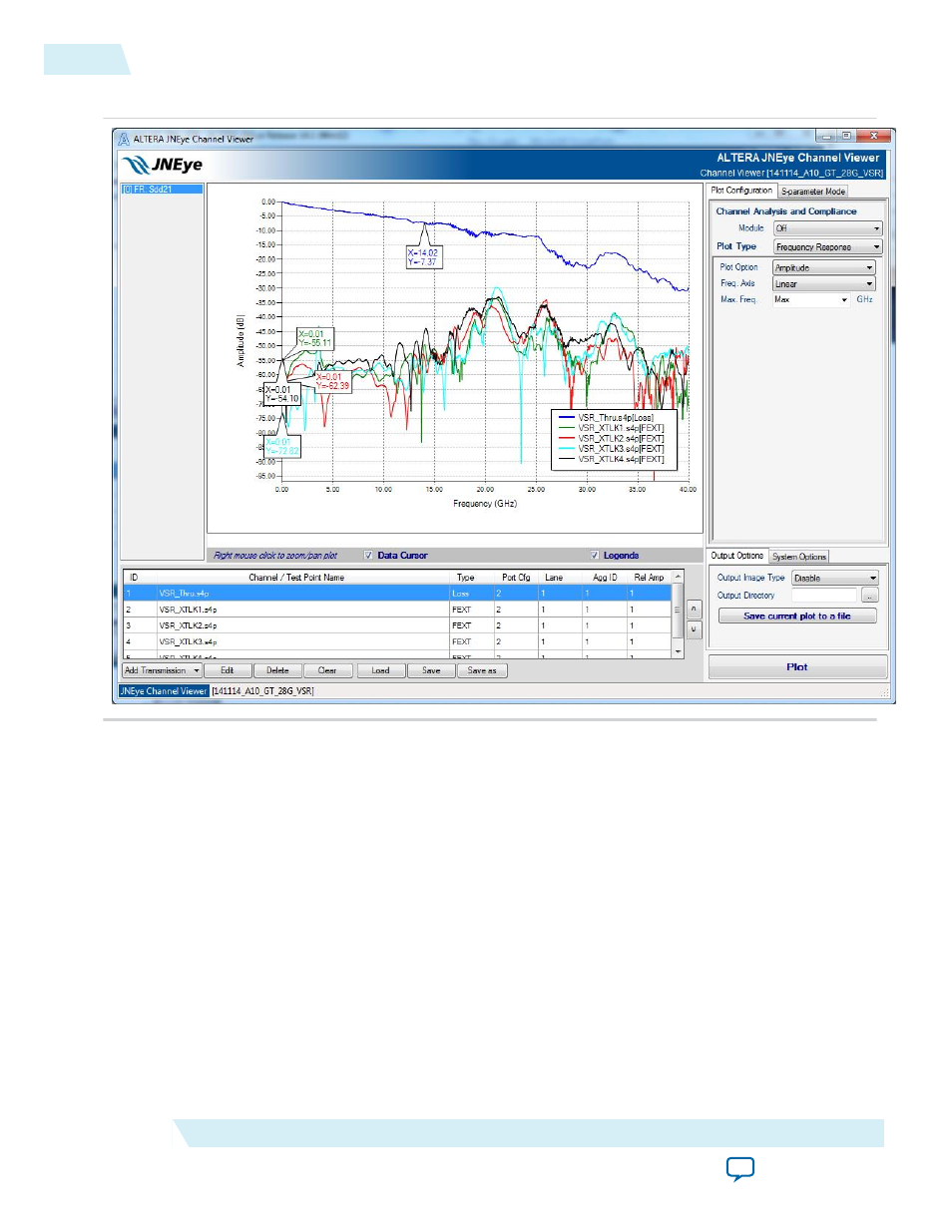
Figure 4-9: Channel Characteristics of Victim and 2 FEXT Channels
Start the channel simulation by clicking Simulate in the lower right corner of the JNEye Control Module.
The JNEye Simulation Engine excises all the models and generates eye diagrams at test points and inside
the receiver (after CTLE and DFE).
A goal of this tutorial was for JNEye to automatically find the optimal link setting for both transmitter and
receiver. In the simulation time, the progress bar flashes multiple times, indicating the JNEye Simulation
Engine is exploring the solution space. The link performance and result of the final setting is shown in a
JNEye Data View.
At TX output, which is located after the Altera Arria 10 GT transmitter output pin (after the TX package
model), the results are shown in the following figure. JNEye found the optimal TX-FIR setting: Pre-tap 2
= 1, Pre-tap 1 = –6, Post-Tap 1 = –13, and Post-Tap 2 = 4. The configured transmitter generates ~0.32
UI of jitter at BER = 10
–15
. This set of TX outputs is measured with the transmitter’s intrinsic jitter and
additional sinusoidal jitter using the ideal clock reference.
4-10
Analysis
UG-1146
2015.05.04
Altera Corporation
Tutorial: 28 Gbps OIF VSR Link with Arria 10 GT