Adding the external i2c master module – Altera Hybrid Memory Cube Controller User Manual
Page 24
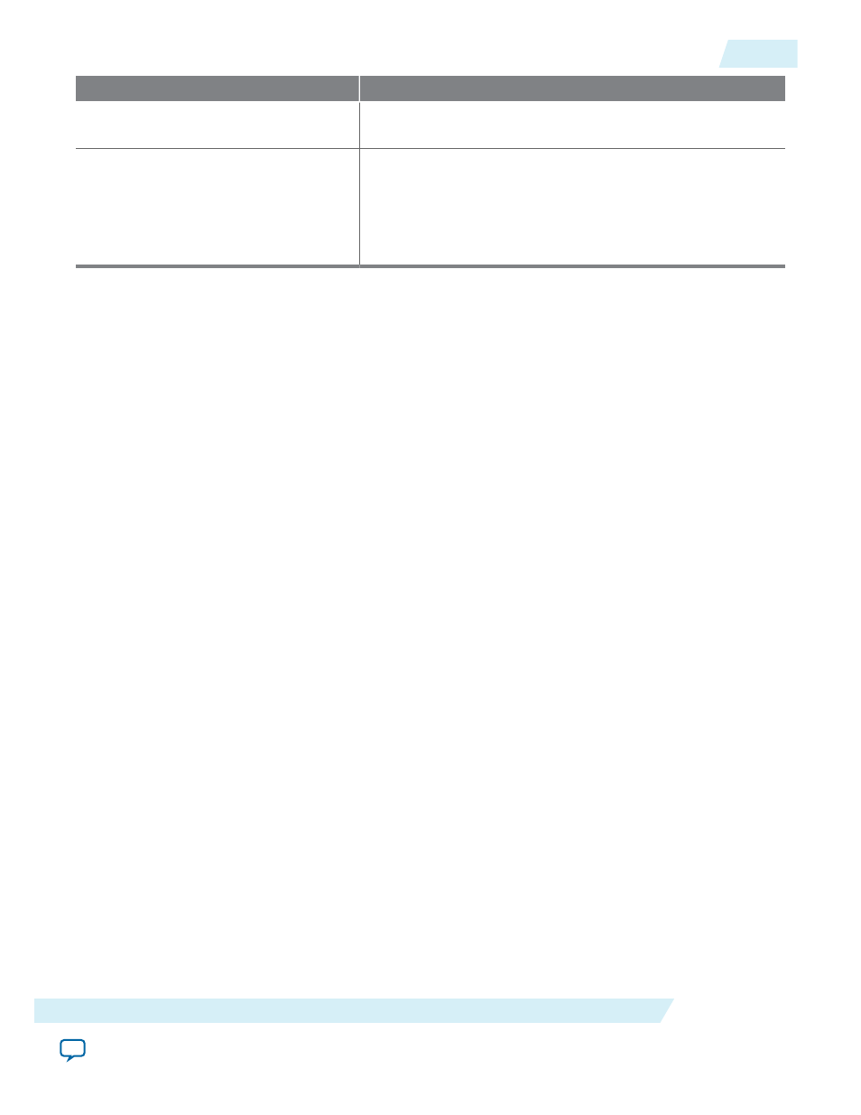
HMC Controller Signal
Connects to TX PLL Signal
pll_powerdown
output signal
pll_powerdown
reset pin of the external PLLs for all of the
HMC lanes.
pll_cal_busy
input signal
Logical OR of the
pll_cal_busy
output signals of the external
PLLs for all of the HMC lanes.
In the case of xN bonding, the single external PLL
pll_cal_
busy
output signal connects directly to the
pll_cal_busy
input
pin of the HMC Controller IP core.
User logic must provide the AND and OR functions and connections.
Related Information
•
•
Signals on the Interface to the External PLLs
on page 4-15
•
HMC Controller IP Core Example Design
The HMC Controller example design provides an example of how to connect external PLLs to your
HMC Controller IP core.
•
Describes the requirement that your IP core lanes configure a maximum of three transceiver blocks.
•
Information about the bonding configurations and the correspondence between PLLs and transceiver
channels, and information about how to configure an external PLL for your own design. You specify
the bonding mode in the PLL parameter editor.
Adding the External I
2
C Master Module
The HMC Controller IP core requires that you instantiate an external I
2
C master module in your design.
Your design must include this module to initialize the HMC device to which your IP core connects.
The I
2
C master module in your system must load the HMC device configuration registers according to
the initialization requirements of the specific HMC device in your system.
The HMC specification requires that you set the HMC device
REGISTER REQUEST commands
register to
the value of
Init Continue
after sending the commands to initialize the HMC. Therefore, the I
2
C master
module must set this register to indicate successful completion of the HMC device configuration register
load sequence.
UG-01152
2015.05.04
Adding the External I
2
C Master Module
2-15
Getting Started with the HMC Controller IP Core
Altera Corporation