LINK Systems 5100-8 Tonnage & Analog Signal Monitor User Manual
Page 74
Doc
#:
L-802-1110 Page
72 Rev.
02
or PNP on a channel by channel basis and provide powerful die protection functions. Refer to the Die
Protection manual for details on operation.
NOTE: The +24V pin on the 5100-8C option connector may be used to power
die protection sensors as well as the relay output board described below.
Draw no more than 0.8 amps from the +24V pin for this purpose. In
the vast majority of cases this will be more than enough current to power
four sensors. If more current is required, a separate 24 volt supply will
need to be provided. If a separate supply is used, make sure the ground
of this supply is tied to one of the COM pins on the 5100-8C option
connector.
The programmable limit switch functions of this option are accessed through the LIMIT SWITCH
softkey on the main screen (see Figure 4 on page 13). If dedicated limit switches are already installed,
then the channels supplied by the tonnage monitor will appear as the last page of channels in the screen.
Instead of the regular limit switch numbers, these channels will be identified as “Ton Mon Limit Switch
Outputs” with channels “O1” to “O4” (this matches the labeling on the tonnage monitor faceplate).
Unlike the 5100 series dedicated limit switch modules, the outputs for this option are sinking outputs
instead of electro-mechanical or solid state relays (see “5100-8C Option Connector” in Figure 22 on
page 52 for the pinout).
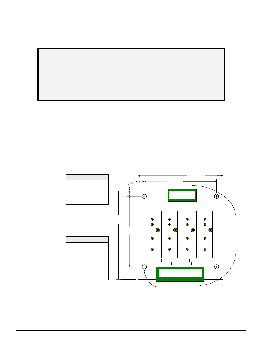
The sinking outputs
from the tonnage
monitor module can
directly drive some
loads - such as PLC
inputs. For
interfacing to loads
that need more than
sinking outputs,
Link makes the
802-5B board to
provide four solid
state relays for
driving various AC
or DC loads. Figure
42 shows the pinout
and mounting
dimensions of this
board. Note that the
relays shown on the
board are relay
sockets, and the customer can populate them with any combination of AC and DC solid state relays.
CON9
1 2 3 4 5
CON10
1 2 3 4 5 6 7 8
Fuse 1
Fuse 1
Fuse 2
Fuse 2
Fuse 3
Fuse 3
Fuse 4
Fuse 4
802-5B
Re
lay
1
Rel
a
y
2
Re
lay
3
Rel
a
y
4
2.60”
(66.0 mm)
2.60”
(66.0 mm)
3.25”
(82.6 mm)
3.00”
(76.2 mm)
0.20”
(5.1 mm)
.156” dia (4 places)
(4.0 mm)
Allow
approx
1” (25mm)
extra for
pluggable
terminal
strip and
wiring.
CON9
1
2
3
4
5
= 12 to 24 VDC
= Relay 1 Control
= Relay 2 Control
= Relay 3 Control
= Relay 4 Control
CON10
1
2
3
4
5
6
7
8
= Relay 1 Out +
= Relay 1 Out -
= Relay 2 Out +
= Relay 2 Out -
= Relay 3 Out +
= Relay 3 Out –
= Relay 4 Out +
= Relay 4 Out -
Board can be
populated with
a mix of AC and
DC solid state
relays.
Figure 42: 802-5B Solid State Relay Board Dimensions