2 faceplate connections and indicators, 3 wiring power for the module, Faceplate connections and indicators – LINK Systems 5100-8 Tonnage & Analog Signal Monitor User Manual
Page 53: Wiring power for the module, Figure 22: tonnage monitor faceplate, 6 installation, 1 mounting the module
Doc
#:
L-802-1110 Page
51 Rev.
02
6 INSTALLATION
The Tonnage and Analog Signal Monitor module can be used with the OmniLink II Press Automation
Control system or with the OmniLink 5000 Press Control system. In both cases, the unit is tied to the
control system with a high speed serial bus.
6.1 Mounting the Module
The Tonnage and
Analog Signal Monitor
module can be mounted
in the press control
enclosure or in its own
enclosure. If the unit is
to be mounted in a
location subject to
shock and vibration,
shock mounts are
required. Either the
card rack assembly can
be shock mounted or
the enclosure in which
it is installed can be
shock mounted.
In selecting the
mounting location, the
wiring connections for
the unit should be
considered as discussed
in section 6.4. After the
mounting location has
been determined, the
card rack assembly can
be secured with four
screws. Mounting
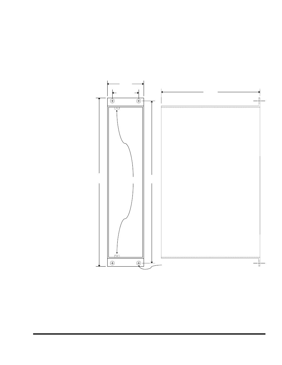
dimensions are shown
in Figure 21. Note that
even though the card
rack is 6.1 inches deep,
an additional 1.5 inches should be set aside for the connectors and wiring that connect to the faceplate of
the unit.
C
L
C
L
C
L
C
L
C
L
C
L
6.1in
(155mm)
10.0in
(254mm)
10.50in
(267mm)
1.625in
(41.3mm)
2.25in
(57mm)
0.267in dia. (4 places)
(6.78mm)
Card
Guides
Figure 21: Unit Mounting Dimensions
To assemble the module, simply slide the Tonnage Monitor module into the single slot card rack. The
module slides into two card guides in the rack, and is held in place with two knurled screws at the top
and bottom of the module.