4 wiring high speed serial bus cable, Wiring high speed serial bus cable, 2 faceplate connections and indicators – LINK Systems 5100-8 Tonnage & Analog Signal Monitor User Manual
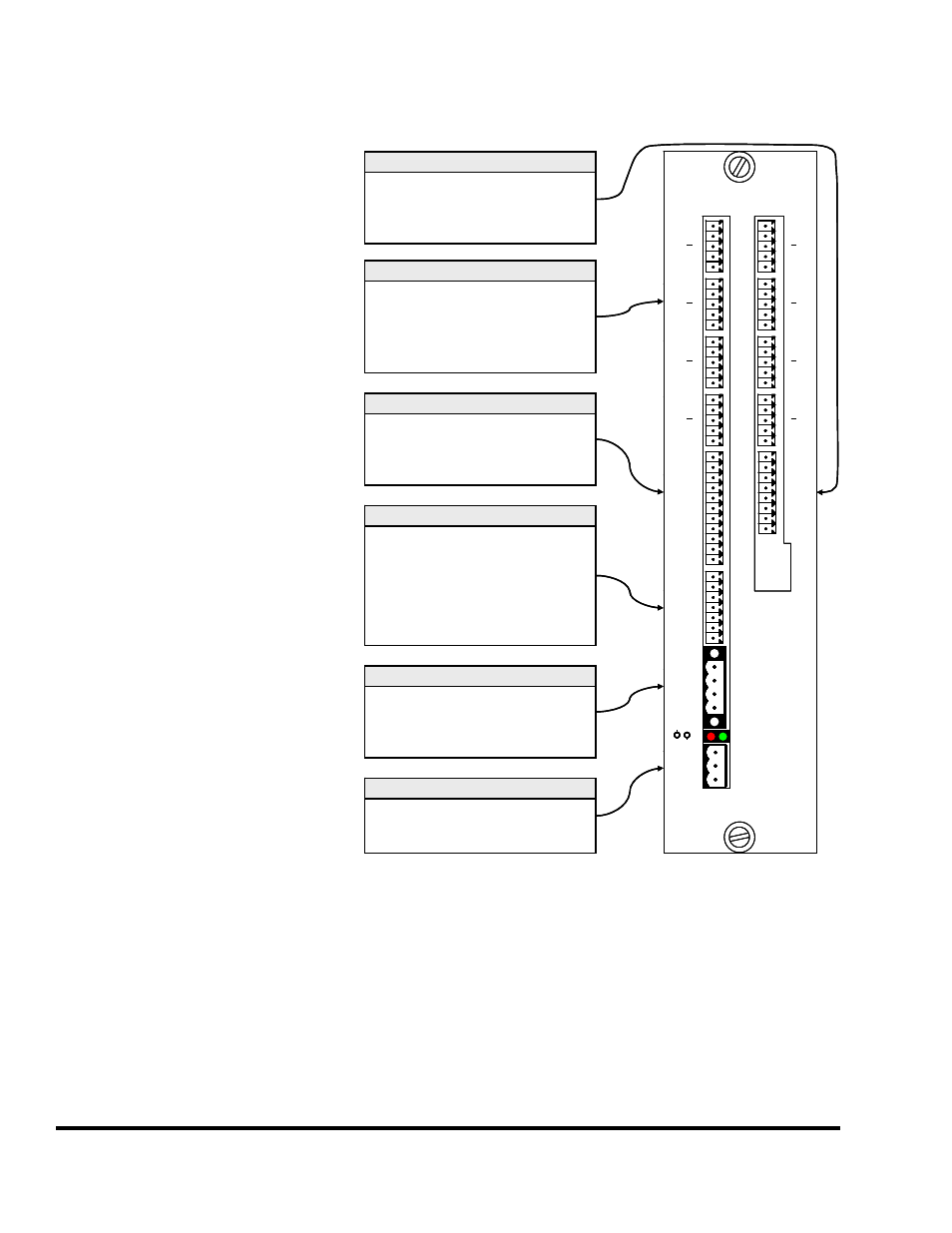
Page 54: 3 wiring power for the module, Figure 22: tonnage monitor faceplate
Doc
#:
L-802-1110 Page
52 Rev.
02
6.2 Faceplate Connections and Indicators
The faceplate of the Tonnage and
Analog Signal module is labeled for
the connectors that provide for field
connection of devices and wiring back
to the OmniLink controller. The CH1,
CH2, CH3, CH4, CH5, CH6, CH7,
and CH8 connectors are strain gage
inputs (CH5 through CH8 are part of
the 5100-8A option and can read
voltage and current output sensors in
addition to strain gage). The 5100-8A
Option Connector provides 4 outputs
and one opto-isolated input for use
with the analog measurement function
of the option (see section 8.1 on page
69 for information on this option).
The 5100-8C Option Connector
provides connections and power for 4
optional programmable limit switch
outputs and 4 die protection inputs (see
section 8.2 on page 71 for information
on this option). The serial port
connector is used to connect to motor
drives in conjunction with the 5100-
8A option for in-die on-the-fly
adjustment. The High Speed Serial
Bus connector is where the unit
communicates with the operator
terminal and control. The Power
Connector provides the unit with
operating power. There are also two
LED indicators. The red indicator is
lit when the unit is providing
termination to the high speed serial bus
(see section 6.5 on page 54). The
green indicator shows the power status
of the unit and should be steady-on. If blinking, the unit likely has a hardware fault. At a minimum,
The Power Connector, High Speed Serial Bus, and two or more strain gages must be connected for
proper operation.
TONNAGE & ANALOG
SIGNAL MONITOR
C
H
1
C
H
2
C
H
3
C
H
4
C
H
5
C
H
6
C
H
7
C
H
8
R
+
C
S
R
+
C
S
R
+
C
S
R
+
C
S
COM
COM
O1
O2
O3
O4
I1
I2
I3
I4
+24V
TX
RX
GND
R+
R-
T+
T-
COM
O5
O6
O7
O8
I5A
I5B
+24V
SHLD
GND
CANH
CANL
L1
NEU
GND
TERM
PWR
R
+
C
S
R
+
C
S
R
+
C
S
R
+
C
S
Strain Gage Wiring
R = VRef = Reference Voltage
+ = SIG+ = Signal Positive
- = SIG- = Signal Negative
C = GND = Common
S = SHLD = Shield
Power Connector
L1
NEU
GND
= 88-264VAC Line
= 88-264VAC Neutral
= Ground
High Speed Serial Bus
SHLD
GND
CANH
CANL
= Shield
= Blue
= Orange
= White
5100-8C Option Connector
COM
O1 to O4
I1 to I4
+24V
= Common
= PLS Outputs 1 to 4
= DP Inputs 1 to 4
= 24 Volts DC Output
Serial Port
TX
RX
GND
R+
R-
T+
T-
= RS232 Transmit
= RS232 Receive
= Ground
= RS485 Receive +
= RS485 Receive –
= RS485 Transmit +
= RS485 Transmit -
5100-8A Option Connector
COM
O5 to O8
I5A, I5B
+24V
= Common
= Outputs 5 to 8
= Input 5
= 24 Volts DC Output
TONNAGE & ANALOG
SIGNAL MONITOR
C
H
1
C
H
2
C
H
3
C
H
4
C
H
5
C
H
6
C
H
7
C
H
8
R
+
C
S
R
+
C
S
R
+
C
S
R
+
C
S
COM
COM
O1
O2
O3
O4
I1
I2
I3
I4
+24V
TX
RX
GND
R+
R-
T+
T-
COM
O5
O6
O7
O8
I5A
I5B
+24V
SHLD
GND
CANH
CANL
L1
NEU
GND
TERM
PWR
R
+
C
S
R
+
C
S
R
+
C
S
R
+
C
S
TONNAGE & ANALOG
SIGNAL MONITOR
C
H
1
C
H
2
C
H
3
C
H
4
C
H
5
C
H
6
C
H
7
C
H
8
R
+
C
S
R
+
C
S
R
+
C
S
R
+
C
S
R
+
C
S
R
+
C
S
R
+
C
S
R
+
C
S
R
+
C
S
R
+
C
S
R
+
C
S
R
+
C
S
COM
COM
O1
O2
O3
O4
I1
I2
I3
I4
+24V
TX
RX
GND
R+
R-
T+
T-
COM
O5
O6
O7
O8
I5A
I5B
+24V
SHLD
GND
CANH
CANL
L1
NEU
GND
TERM
PWR
TERM
PWR
R
+
C
S
R
+
C
S
R
+
C
S
R
+
C
S
R
+
C
S
R
+
C
S
R
+
C
S
R
+
C
S
R
+
C
S
R
+
C
S
R
+
C
S
R
+
C
S
Strain Gage Wiring
R = VRef = Reference Voltage
+ = SIG+ = Signal Positive
- = SIG- = Signal Negative
C = GND = Common
S = SHLD = Shield
Strain Gage Wiring
R = VRef = Reference Voltage
+ = SIG+ = Signal Positive
- = SIG- = Signal Negative
C = GND = Common
S = SHLD = Shield
Power Connector
L1
NEU
GND
= 88-264VAC Line
= 88-264VAC Neutral
= Ground
Power Connector
L1
NEU
GND
= 88-264VAC Line
= 88-264VAC Neutral
= Ground
High Speed Serial Bus
SHLD
GND
CANH
CANL
= Shield
= Blue
= Orange
= White
High Speed Serial Bus
SHLD
GND
CANH
CANL
= Shield
= Blue
= Orange
= White
5100-8C Option Connector
COM
O1 to O4
I1 to I4
+24V
= Common
= PLS Outputs 1 to 4
= DP Inputs 1 to 4
= 24 Volts DC Output
5100-8C Option Connector
COM
O1 to O4
I1 to I4
+24V
= Common
= PLS Outputs 1 to 4
= DP Inputs 1 to 4
= 24 Volts DC Output
Serial Port
TX
RX
GND
R+
R-
T+
T-
= RS232 Transmit
= RS232 Receive
= Ground
= RS485 Receive +
= RS485 Receive –
= RS485 Transmit +
= RS485 Transmit -
Serial Port
TX
RX
GND
R+
R-
T+
T-
= RS232 Transmit
= RS232 Receive
= Ground
= RS485 Receive +
= RS485 Receive –
= RS485 Transmit +
= RS485 Transmit -
5100-8A Option Connector
COM
O5 to O8
I5A, I5B
+24V
= Common
= Outputs 5 to 8
= Input 5
= 24 Volts DC Output
5100-8A Option Connector
COM
O5 to O8
I5A, I5B
+24V
= Common
= Outputs 5 to 8
= Input 5
= 24 Volts DC Output
Figure 22: Tonnage Monitor Faceplate
6.3 Wiring Power for the Module
The Tonnage & Analog Signal Monitor module receives its power from the Power Connector as shown
in Figure 22. The connector used for this is a double connection plug as shown in Figure 23. This
allows power to be “daisy-chained” from module to module for convenience. However, unlike the high