4 wiring high speed serial bus cable, Figure 23: power connector – LINK Systems 5100-8 Tonnage & Analog Signal Monitor User Manual
Page 55
Doc
#:
L-802-1110 Page
53 Rev.
02
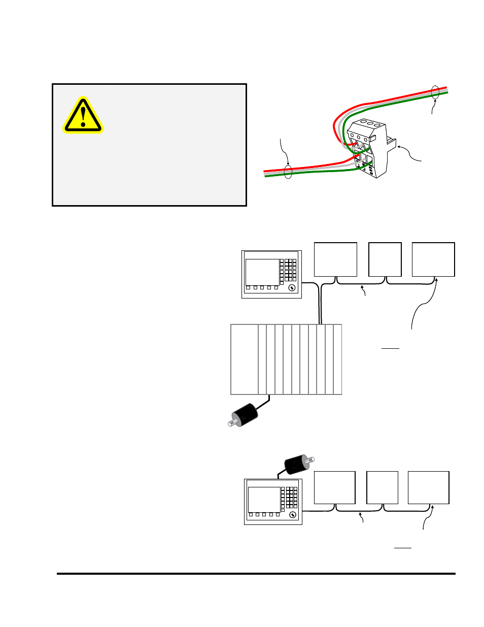
speed serial cable, the power cable does not have to be “daisy-chained”. Power can be taken from any
convenient source. The power wiring should be at least 16 GA.
Power To
Next Module
(16 GA red, white,
And green wires)
Power From
Last Module
(16 GA red, white,
and green wires)
Power
Connector
For Module
Power To
Next Module
(16 GA red, white,
And green wires)
Power From
Last Module
(16 GA red, white,
and green wires)
Power
Connector
For Module
WARNING!
While the Tonnage & Analog
Signal Monitor (and most newer
Link products) has a “universal
power supply” and can operate
from 88-264VAC, some older
modules operate on 110VAC
only. Verify the power
requirements of all modules in
the system before “daisy-
chaining” the power from a
higher voltage source!
Figure 23: Power Connector
6.4 Wiring High Speed Serial
Bus Cable
OmniLink II LCD
Operator Terminal
OTHER
OMNILINK II
OPTIONS
(If Present)
High Speed
Serial Bus
Cable
OMINLINK 5000
PRESS CONTROL
Tonnage
& Analog
Signal
Monitor
OTHER
OMNILINK II
OPTIONS
(If Present)
Pow
e
r
C
o
nn
ec
ti
o
n
Mod
u
le
L
ogi
c Mo
dul
e
R/D Mo
dul
e
1st Inpu
t
Mo
d
u
le
2
n
d I
n
p
u
t
Mo
du
le
Ou
tp
u
t Dri
v
e
Hi Sp
eed
In
ter
fa
c
e
Resolver/Encoder
NOTE: Last Option on
High Speed Serial Bus
MUST be terminated
(see text for details)
OmniLink II LCD
Operator Terminal
OmniLink II LCD
Operator Terminal
OTHER
OMNILINK II
OPTIONS
(If Present)
High Speed
Serial Bus
Cable
OMINLINK 5000
PRESS CONTROL
Tonnage
& Analog
Signal
Monitor
OTHER
OMNILINK II
OPTIONS
(If Present)
Pow
e
r
C
o
nn
ec
ti
o
n
Mod
u
le
L
ogi
c Mo
dul
e
R/D Mo
dul
e
1st Inpu
t
Mo
d
u
le
2
n
d I
n
p
u
t
Mo
du
le
Ou
tp
u
t Dri
v
e
Hi Sp
eed
In
ter
fa
c
e
Resolver/Encoder
NOTE: Last Option on
High Speed Serial Bus
MUST be terminated
(see text for details)
The high speed serial bus cable is a critical
part of the system. Communications with
the operator terminal for settings and
status, crank angle and mode information
from the control, and stop signals to the
control are all sent through this
communications link.
As mentioned earlier, the Tonnage &
Analog Signal Monitor can be used with
both the System 5000 Press Control as
well as the OmniLink II Automation
Control.
When used with the System 5000 Press
control, the high speed serial wiring
should be run in a fashion similar to
Figure 24.
Figure 24: System 5000 High Speed Bus Wiring
OmniLink II Press Automation Control
OmniLink II LCD
Operator Terminal
Resolver or
Resolver/Encoder
OTHER
OMNILINK II
OPTIONS
(If Present)
High Speed
Serial Bus
Cable
OMINLINK II PRESS
AUTOMATION CONTROL
Tonnage
& Analog
Signal
Monitor
OTHER
OMNILINK II
OPTIONS
(If Present)
NOTE: Last Option on
High Speed Serial Bus
MUST be terminated
(see text for details)
OmniLink II Press Automation Control
OmniLink II LCD
Operator Terminal
OmniLink II Press Automation Control
OmniLink II LCD
Operator Terminal
OmniLink II LCD
Operator Terminal
Resolver or
Resolver/Encoder
OTHER
OMNILINK II
OPTIONS
(If Present)
High Speed
Serial Bus
Cable
OMINLINK II PRESS
AUTOMATION CONTROL
Tonnage
& Analog
Signal
Monitor
OTHER
OMNILINK II
OPTIONS
(If Present)
NOTE: Last Option on
High Speed Serial Bus
MUST be terminated
(see text for details)
Figure 25 shows a similar setup using the
OmniLink II Press Automation Control.
While the tonnage monitor module is
shown in the middle of the “string” of
options in both of these examples, it could
also be the last unit in the line.
Figure 25: Automation Control High Speed Bus Wiring