8 optional components, 1 the 5100-8a channel expansion option, 8 optional – LINK Systems 5100-8 Tonnage & Analog Signal Monitor User Manual
Page 70: Components, The 5100-8a channel expansion option, Figure 39: 5100-8 circuit board option connectors, 69 for inform, Figure 37: load cell hit with bad tie-rod tension, Figure 38: load cell hit with good tie-rod tension
Doc
#:
L-802-1110 Page
68 Rev.
02
equal loads are on the load cells. If the channels with much higher calibration numbers now give
tonnage readings much larger than the channels with lower calibration numbers improper tie rod tension
is indicated.
Channel 1
Tonnage
EXIT
NEXT
CHANNEL
SELECT
PEAK/DATA
WINDOW
Use the
and keys to move the graph cursor
Use the and keys to move the parameter cursor
OVERLAY
GRAPHS
Angle: 180.0°
Tonnage: 92.8 Tons
Cursor Readout
CHANNEL 1 TONS - PEAK SETPOINTS
DW 1
DW 2
DW 3
DW 4
PEAK
INFO
Start
End
100.0
90.0
80.0
70.0
60.0
50.0
40.0
30.0
20.0
10.0
0.0
-10.0
-20.0
-30.0
-40.0
-50.0
160.0°
180.0°
200.0°
160°
200°
View Pts: 1085
ENTER PAN
ZOOM MODE
SEND
GRAPH
SHOW REF
GRAPH
HI LIM
LO LIM
RV LIM
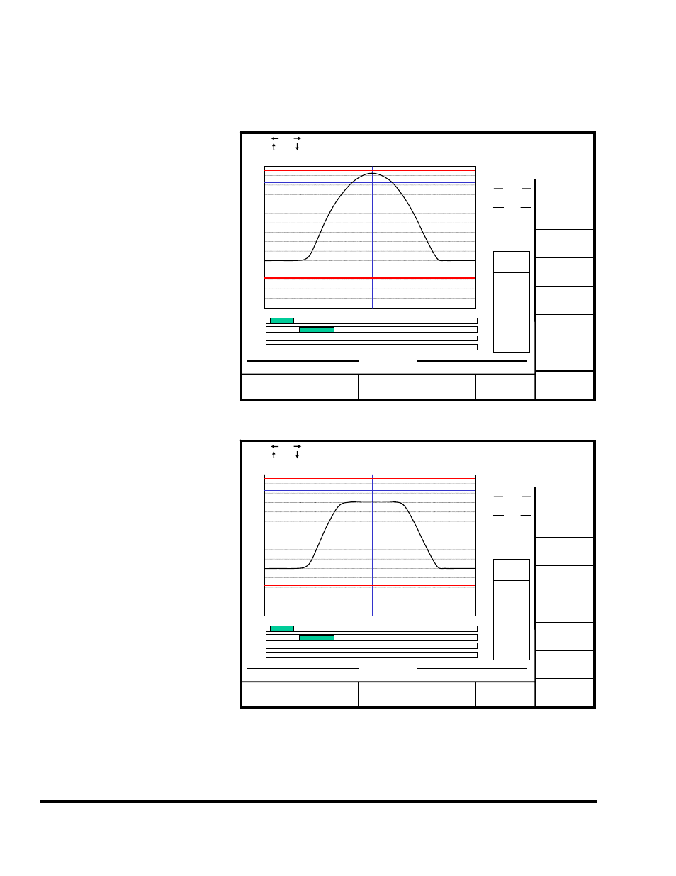
Another way to check for loose tie
rods is to check the tonnage graph
when hitting load cells at near
machine rating. Figure 38 shows a
tonnage graph of a typical load cell
hit on a machine with tie rods that
are in proper tension. There is a
characteristic “hump” shape with a
rounded top. Actual hits may not
be quite as smooth but should have
the same general shape. Figure 37
shows the characteristic shape for a
channel on an upright with a loose
tie rod. The “hump” flattens out at
around 70 tons. This means that
instead of the 150 tons of preload
the tie rod should have, it had only
70 tons of preload. Not only does
this result in the inability of the
tonnage monitor to read the proper
tonnage on that channel, but this
can cause all kinds of machine,
tooling, and quality problems
because whenever the channel
exceeds 70 tons, the upright is
actually separating from the bed
and crown of the press. This can
cause hit to hit variation in the
alignment of the press itself. Note
that the flattening of the “hump”
can occur at almost any level
depending on how loose tie rods
are.
Channel 1
Tonnage
EXIT
NEXT
CHANNEL
SELECT
PEAK/DATA
WINDOW
Use the
and keys to move the graph cursor
Use the and keys to move the parameter cursor
OVERLAY
GRAPHS
Angle: 180.0°
Tonnage: 72.1 Tons
Cursor Readout
CHANNEL 1 TONS - PEAK SETPOINTS
DW 1
DW 2
DW 3
DW 4
PEAK
INFO
Start
End
100.0
90.0
80.0
70.0
60.0
50.0
40.0
30.0
20.0
10.0
0.0
-10.0
-20.0
-30.0
-40.0
-50.0
160.0°
180.0°
200.0°
160°
200°
View Pts: 1085
ENTER PAN
ZOOM MODE
SEND
GRAPH
SHOW REF
GRAPH
HI LIM
LO LIM
RV LIM
L
95.0
82.3
18.2
CHANGE
NUMBER
GRAPH
SETTINGS
SHOW BY
TIME
Cap Pts: 3143
Figure 37: Load Cell Hit with Bad Tie-Rod Tension
L
95.0
82.3
18.2
CHANGE
NUMBER
GRAPH
SETTINGS
SHOW BY
TIME
Cap Pts: 3143
Figure 38: Load Cell Hit with Good Tie-Rod Tension