6 the machine rating de-rate table screen, The machine rating de-rate table screen, Figure 19: example tonnage de-rate curve – LINK Systems 5100-8 Tonnage & Analog Signal Monitor User Manual
Page 49: 5 the tonnage monitor calibration screen, Figure 18: tonnage monitor calibration screen
Doc
#:
L-802-1110 Page
47 Rev.
02
violates the low limits. When this setting is “Yes”, the tonnage monitor will automatically bypass the
low limits while in a setup mode. This happens with no operator intervention and clears itself when
going back to a production mode. While in setup mode, the low limits are clearly indicated as off in
each channel status line with “Setup Mode Low Lim OFF” displayed in yellow. The benefit of this
setting is that high and reverse limits are not bypassed, thus providing greater machine protection, and
that the operator does not have to remember to turn the low limits back on when going to production
mode.
4.4.16 Resetting Alarm Counters
The alarm counters that are displayed in the Tonnage Monitor Diagnostics screen (see section 3.3 on
page 27) can be reset by pressing the CLEAR ALARM COUNTERS softkey. The OIT will ask for
confirmation before clearing the counts.
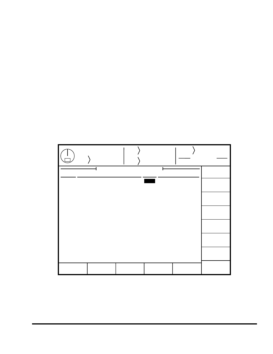
4.5 The Tonnage Monitor Calibration Screen
Press the SELECT key to the right of the “Tonnage Monitor Calibration” in the Tonnage Monitor
Configuration screen as shown in Figure 16 to display the screen shown in Figure 18.
Stroke
Mode
Single Stroke
Drive
Speed
Stroke
Speed
SPM
SPM
0
0
Order
Counter
Current Status
Counter OFF
EXIT
0
0
Program/Run Switch
TOP
Tonnage
Monitor
Left Rear
200.0
Tonnage Monitor Channel Calibration
200.0
1
CHANGE
NUMBER
Channel
Description
Cal. #
Tonnages
Right Rear
Left Front
Right Front
200.0
200.0
2
3
4
Total
76.7 Tons
76.8 Tons
77.2 Tons
76.8 Tons
307.5 Tons
Stroke
Mode
Single Stroke
Drive
Speed
Stroke
Speed
SPM
SPM
0
0
Order
Counter
Current Status
Counter OFF
EXIT
0
0
Program/Run Switch
TOP
Tonnage
Monitor
Left Rear
200.0
Tonnage Monitor Channel Calibration
200.0
1
CHANGE
NUMBER
Channel
Description
Cal. #
Tonnages
Right Rear
Left Front
Right Front
200.0
200.0
2
3
4
Total
76.7 Tons
76.8 Tons
77.2 Tons
76.8 Tons
307.5 Tons
Figure 18: Tonnage Monitor Calibration Screen
Changes can be made to the tonnage monitor calibration numbers (gain) with the RUN/PROG keyed
selector switch in the PROG position. Position the editing cursor onto the desired calibration number
and use the numeric keypad to enter the desired value. The press can be operated with the selector
switch in the RUN position and will update the actual peak tonnage measured each stroke. See section 7
on page 63 for calibration procedures.