2 boards and pcms, 2 signaling configuration, 1 ss7 configuration – Dialogic SS7G2X User Manual
Page 136: Boards and pcms, Signaling configuration 7.2.1, Ss7 configuration, Physical configuration, For a, Configured. see, For a more
136
Chapter 7 Configuration Overview
7.1.2
Boards and PCMs
A Signaling Gateway contains a number of SS7 signaling boards located in individual board positions (
).
Signaling boards are managed using the CNBOx commands.
An SS7 signaling board can terminate up to two PCM (
) trunks for connection to either a Signaling End
Point (SEP) or Signaling Transfer Point (STP). When configuring the PCM, the user can specify whether it
should act as E1 or T1 as well as its frame format (
). The configuration of a PCM also
determines whether the port signal is to be used as the external clock synchronization source of the
Signaling Gateway. Each PCM can be assigned a synchronization priority (
) specifying the priority it
has within the Signaling Gateway to receive the external clock for the system. The PCM in the system with
the lowest numbered synchronization priority that is active and in service provides the clocking source for
the Signaling Gateway. If the current PCM providing clock for the system goes out of service, the PCM with
the next highest clock priority that is in service provides clock for the Signaling Gateway. If a PCM’s
synchronization priority is set to 0, that PCM never provides clock for the system.
PCMs are managed using the CNPCx commands.
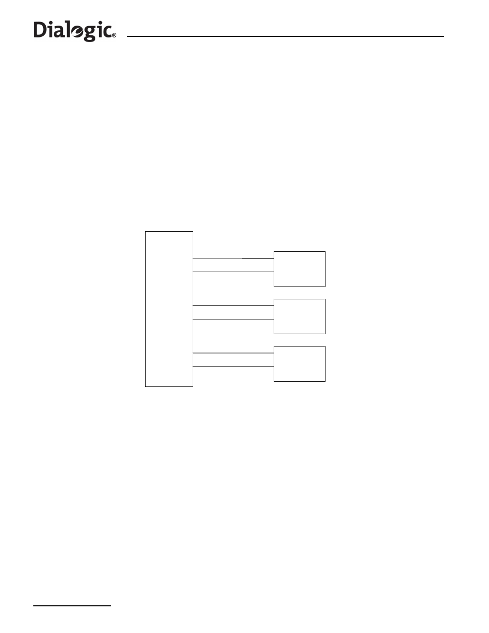
Figure 5. Physical Configuration
demonstrates a Signaling Gateway configured with three boards and six PCMs, four E1 and two T1
connect to primary, secondary and tertiary clock sources. Example MML for the above configuration is:
:
=SPCI2S-4-2,
SIGTYPE
=SS7;
:
=SPCI2S-4-2,
SIGTYPE
=SS7;
:
=SPCI2S-4-2,
SIGTYPE
=SS7;
:
=1-3,
=1;
:
=2-3,
=1;
:
=1-4,
=2;
:
=2-4,
=2;
:
=3-3,
=3;
:
=3-4,
=3;
7.2
Signaling Configuration
7.2.1
SS7 Configuration
A Link Set (
) is the set of signaling links between an Originating Point Code (
) on the Signaling
Gateway and an adjacent Destination Point Code (
). When specifying a link set the user can specify the
MTP type and point code size (
), the SS7 Network Identifier (
belongs in. Link sets are managed using the C7LSx commands.
Secondary
Clock
Source
Tertiary
Clock
Source
Primary
Clock
Source
PCM 1-3
PCM 2-3
PCM 1-4
PCM 2-4
PCM 3-3
PCM 3-4
T1
E1
E1