Temperature compensation, Directions to configure conductivity sensor, E 147 – YSI 5200A User Manual
Page 74
YSI 5200A
147
YSI 5200A
146
In the timed mode, an energized control relay is energized for the configured dose
time, regardless if the sensor value has returned to the set point value. After the
dose time expires, the control relay de-energizes for the configured dwell time.
After the dwell time expires, if the value is still in control range, the control relay
will reenergize. A dwell time must be configured in the timed mode or the control
relay will never de-energize regardless of sensor value.
Temperature Compensation
Conductivity values vary with temperature. Conductivity values are normally
compensated to 25°C. An adjustment of approximately 1.91% per °C is common.
Enter “0.00%” at the temperature compensation menu to disable temperature com-
pensation. “*” is displayed next to a conductivity value at the Run Screen to indicate
temperature compensation is enabled.
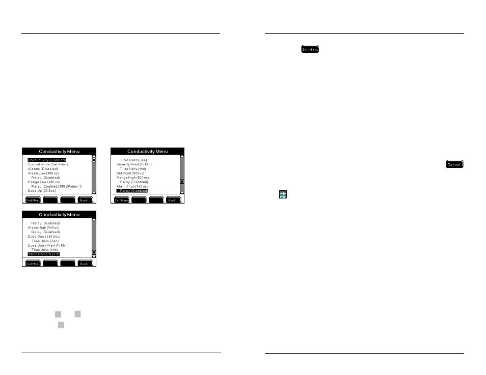
Directions to Configure Conductivity Sensor
1. Connect probe assembly - page 61.
2. Enter Conductivity Sensor Setup menu
Menus →Sensor Setup→Conductivity
3.
Use
▲
and
▼
to scroll and highlight submenus.
4.
Press
to select.
5. Configure submenus.
Configuring the 5200A
6. Press
to save configuration and return to Run Screen.
Notes:
- Conductivity set points are always entered in µS (multiply mS value X
1000 to obtain µS value).
- Only whole numbers can be configured for conductivity set point, control,
and alarm values.
- See 30 Second Sensor Hold Off - page 141.
- Active dosing timers are reset after systemwide events. Systemwide events
de-energize relays. Example - conductivity dose up relay is configured
for two (2) minutes. Energized dose up relay de-energizes when 5200A
goes into Svr Hold. The dose up relay had been energized for 15 seconds
before Svr Hold occurred. Svr Hold time is one (1) minute. After Svr Hold
time expires, the control system is reset. If sensor is reporting control
low condition the dose on time will be for two (2) minutes and not the
remaining 45 seconds of the dose up time prior to the Svr Hold.
- Conductivity Control Low Range Low message remains at the
menu when the conductivity system is disabled when a control low relay
is energized. Power cycle the 5200A to clear the control low range mes-
sage at the Msg’s menu.
- AquaManager data log displays 5200A conductivity values in µS to 0.00
resolution.
DO
Menus →Sensor Setup→DO
Read Sensor Setup Control and Alarms - page 132 before configuring DO system.
Salinity & Temperature Compensation for DO Readings
In order to report accurate DO values, the salinity and temperature of the monitored
water must be known. Temperature is measured by the temperature sensor located
on the probe assembly. Salinity is either calculated by the conductivity sensor (see
Salinity - page 153) or by entering a user defined ppt value in the DO menu. If the
salinity system is enabled, then the DO salinity menu is not available to configure.
Notes:
- When conductivity is enabled, salinity is ALWAYS calculated by the con-
ductivity sensor and this value is used to calculate DO mg/L.
- Disabling conductivity requires that a ppt value be entered in the 5200A
DO sensor menu. In this menu, enter the salinity value of the water being
monitored. The acceptable salinity input range is 0-50 ppt.
Configuring the 5200A