Set point control, E 134 – YSI 5200A User Manual
Page 68
YSI 5200A
135
YSI 5200A
134
Set Point Control
Set point control menu options are shown below for an aux analog system.
Control relays configured in the Set Point control mode energize when a user config-
ured control value is received from the input device and is processed by the 5200A.
Control relays can be configured to raise and/or lower Analog Aux device systems,
Conductivity, DO, ORP, pH and/or Temperature systems. High temperature, high
and low pH and high and low conductivity can also be configured for a timed set
point mode - see “Timed and Normal control mode” information included in spe-
cific sensor setup sections that follow. Configure high and/or low alarm systems
to activate peripheral devices and/or to provide alarm notification messages when
alarm condition(s) exist. Configure values outside of acceptable operating control
range as high and low alarm values.
Set Point Control Values
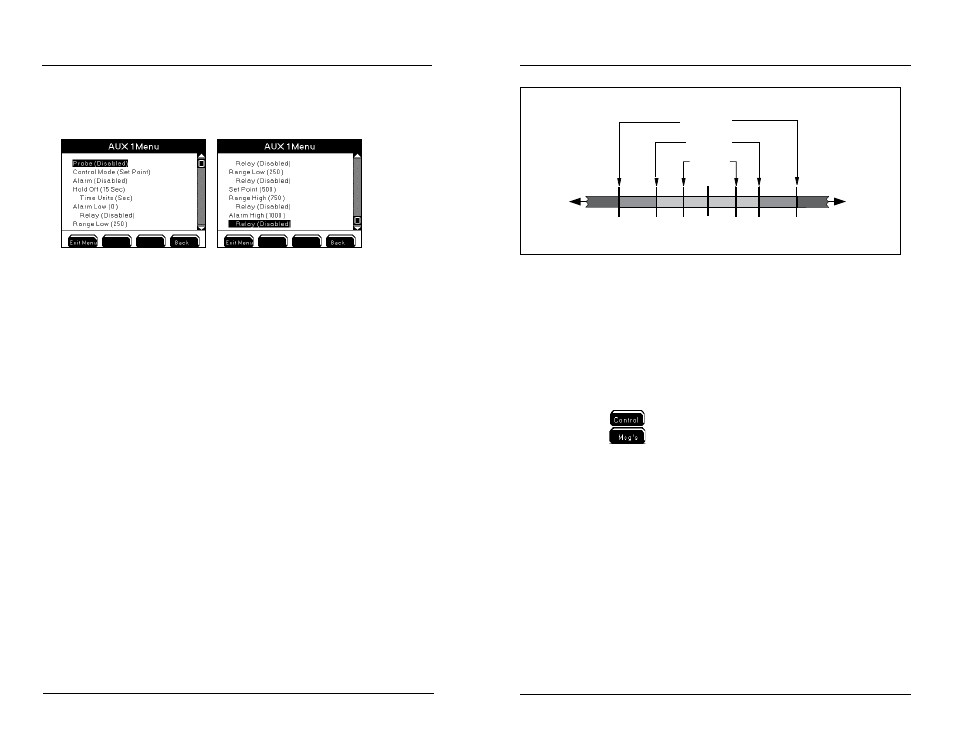
Range low and Range high values set the acceptable operating range for the water
system. Control system(s) do not become active when value(s) are within acceptable
control range. See figure 4.7 - page 135. Enabled control relays energize when the
sensor reports a value ≤ the range low control value or ≥ range high control value.
Control relays are typically wired to devices used to raise or lower certain water
parameters in order to maintain the system as close to set point as possible. Control
relays remain energized until the sensor reports a value ≤ set point (when dosing
down to lower specific water parameter) and/or ≥ set point (when dosing up to
raise specific water parameter). Exception - high temperature, high and low pH and
high and low conductivity may also be configured for a timed set point mode - see
“Timed and Normal control mode” information included in specific sensor setup
sections that follow. Sensor low control range starts at -1 significant digit below set
point value. High control range starts at +1 significant digit above set point value.
Figure 4.7 shows how the 5200A operates based on a set point control sensor setup
configuration. In the example provided DO range low and range low 2 devices will
energize at ≤ 5.0 and ≤4.0 respectively. The alarm low system becomes active at ≤3.5.
Configuring the 5200A
Range #1
Low
Alarm
ON
High
Alarm
ON
High
Range #1
ON
Optimal
S
etpoint
Value
Lower
Parameter
Values
High
Alarm
Setpoint
Low
Alarm
Setpoint
Higher
Parameter
Values
DO Range #2
High
Range #2
ON
Low
Range #1
ON
Low
Range #2
ON
Acceptable
Operating
Range
Temperature have 1 Control Range
DO has 2 Control Ranges
3.5 mg/l 4.0 5.0 8.1 8.5
8.7 8.9
Figure 4.7
Notes:
- Changing control method between PID/PWM and Set Point may result
in invalid set point, control and alarm value configurations. Always
reconfirm control menus configuration when control mode is changed.
- DO systems have two control ranges. They are referred to as Range Low
& Range Low 2 and Range High & Range High 2.
- Control systems remain active when the user is in 5200A menus.
- Control icons display at the Run Screen when relays are energized - see
Icons - page 70.
- Press
at Run Screen to display active sensor and aux system relays.
- Press
at Run Screen to display events created by control and alarm
relays - see Event Log - page 107.
- Control relays are not energized if the 5X00 DO sensor value reads “Over”
or “Under.”
- “Over” and “Under” are not displayed for aux temperature systems when
temperature values are outside the temperature operating range - see
temperature range specification - page 14 Temperature system controls
will not operate correctly when values are outside the temperature op-
erating range.
- See Wire Relays - page 46 for information on wiring control output
devices.
Set Point Alarm Values
Alarm values set the acceptable control range. Alarm system(s) do not become
active when values are within acceptable control range. See figure 4.7 - page 135.
Enable and configure system alarm(s) to activate alarm output devices(s), view
Configuring the 5200A