Step 8 wire communication equipment, Email alarming, Rs232 communication – YSI 5200A User Manual
Page 30
YSI 5200A
59
YSI 5200A
58
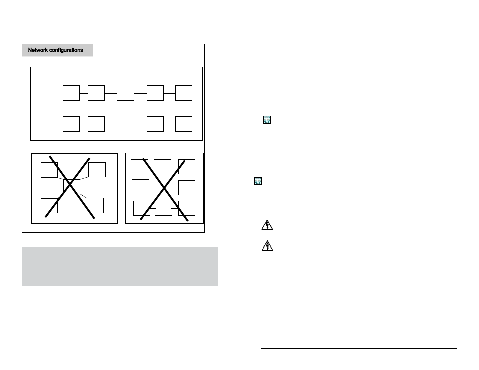
Network configurations
Master
Master
Master
slave
slave
slave
slave
slave
slave
slave
slave
slave
slave
slave
slave
slave
slave
slave
do not wire “star” network
follow master/slave wiring directions figure 3.26
Master
slave
slave
slave
slave
do not wire “loop” network
b
b
good
good
bad
bad
Figure 3.28
Test Network Wiring and Configuration
Apply power to only the master and last slave device on the network. If the master is
not the first physical device on the network, apply power to the master and the first
and last physical slave devices on the network. See Network beginning on page 95.
Step 8 Wire Communication Equipment
Communication equipment must be installed in order to communicate, either lo-
cally or remotely, with the 5200A. The communication connection can be made
locally (RS232) or remotely with a serial to ethernet device. Only one connection
method can be used at a time. AquaManager supports both connection methods.
Installation and Wiring
Notes:
- Firmware can only be uploaded to an instrument using a local RS232 con-
nection. See Update 5200A Firmware - page 112.
- On a network, install and configure RS232 or the serial to ethernet device
hardware on the master node only.
Email Alarming
Email alarming can be configured in one of two ways:
- from a PC running the AutoPoll Program that is included with AquaMan-
ager software (PC must have internet connection). This is referred to as
AquaManager email.
- via a serial to ethernet* device with TCP/IP connection at master 5200A.
This is referred to as 5200A email.
*Serial to ethernet connection requires access to a SMTP server accessible by the
local network.
RS232 Communication
Use Category 5e patch cable from RS232 port at location H - figure 3.29 of I/O
board to PC using RJ45 to DB9 adapter.
Directions to Wire Direct RS232 PC Connection
WARNING: Disconnect external power to the unit before wiring
.
AVERTISSEMENT : déconnectez l’alimentation externe de l’unité avant d’effectuer
un câblage quelconque.
1. Perform steps 1 - 4 of 5200A installation and steps 5, 6 and 7 as required
for the application.
2. Open front panel - page 39.
3. Feed direct connect cable through drilled hole of rubber grommet and
to location H.
4. Run high and low voltage cables through separate bulkhead and con-
duit.
5. Connect one end of communication cable to RJ45 at location H. Connect
other end to PC com port using RJ45 to DB9 adapter.
Installation and Wiring