YSI 5200A User Manual
Page 29
YSI 5200A
57
YSI 5200A
56
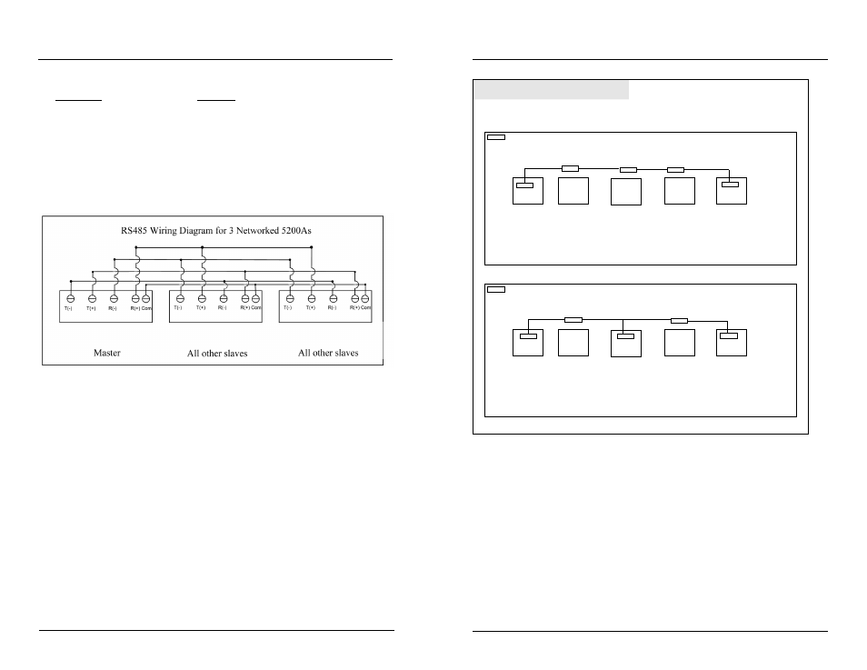
Wire all slaves as follows:
Wire Color
Terminal
solid blue
T (-)
white with blue stripe
T (+)
solid orange
R (-)
white with orange stripe
R (+)
green
Communications
Common
(C)
Figure 3.26 is a wiring diagram for the most common 5200A network configuration
where a master 5200A is the first physical device in the network.
Figure 3.26
6. Wire all network terminal strips prior to network testing, but only con-
nect a network terminal strip to the first and last devices on the network
(*see note below). Configure network menu and follow testing procedure
as described - page 96. Slave devices are tested one by one as they are
added to the network. Network testing cannot be done if stubs exist (**
see note below).
Notes:
- *If the master is not the first physical device on the network, place network
terminal strip on the master and on the first and last physical devices on
the network. (In this case two slaves will need to be tested at the same
time.) - figure 3.27.
- **A stub is created when the last wired network terminal strip is not con-
nected to a network slave - figure 3.24.
Installation and Wiring
master
Testing network configurations
slave
master
slave
slave
slave
-represents wired network termination strip
-terminal strips that appear within master/slave box represent terminal strips that are physically
connected to device
-terminal strips that appear outside slave box represent terminal strips not connected to device
When master is first physical device on network, as shown above, connect terminal strip to master and last
slave (slave 4) to begin network testing. Terminal strips for slaves located between the master and the last
slave are then connected, one, by one beginning with slave device furthest from master and continuing to
slave devices closest to master. Testing in the above graphic would occur first with slave 4, then slave 3,
then slave 2, ending with slave 1.
slave
slave
slave
slave
-represents wired network termination strip
-terminal strips that appear within master/slave box represent terminal strips that are physically
connected to device
-terminal strips that appear outside slave box represent terminal strips not connected to device
When master is not the first physical device on network, as shown above, connect terminal strip to master
and outer most slaves (slaves 1 and 4) to begin network testing. Testing in above graphic would occur first
with slaves 1 and 4, and then continuing by testing slave device 2, or slave device 3 until all network
wiring is tested.
Use below network wiring testing method when master is not first physical device on network.
Use below network wiring testing method when master is first physical device on network.
Follow wiring instructions below to avoid testing network wiring with stubs.
1
2
3
4
1
2
3
4
Figure 3.27
7. Close front panel - page 40.
5200A networks must be configured point-to-point (instrument-to-instrument).
Network wiring cannot contain loops, stars, or stubs - figure 3.28.
Installation and Wiring