Menu maps – YSI 5200A User Manual
Page 108
YSI 5200A
215
YSI 5200A
214
continued next page
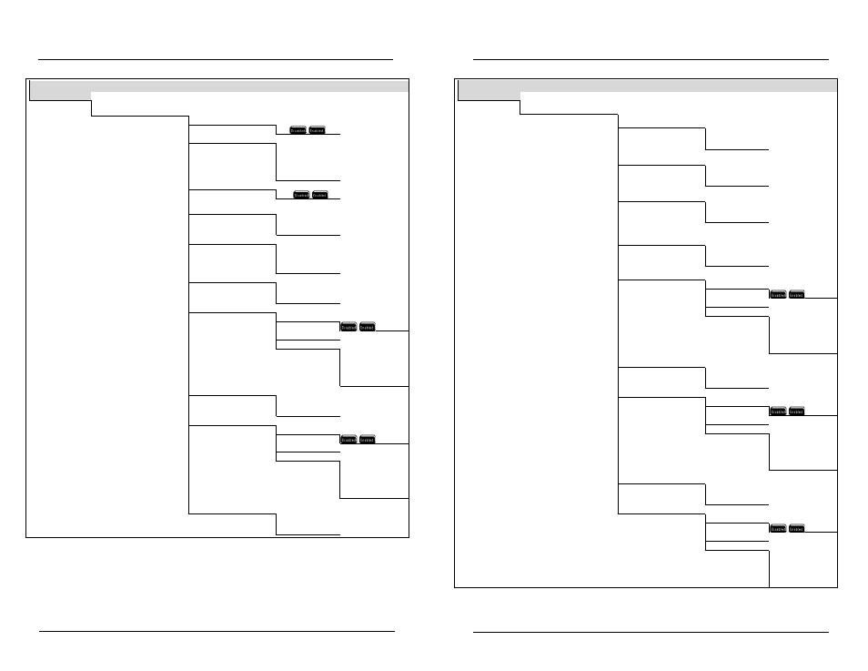
Menu Maps
Run Screen
→
Menus
→
Sensor Setup
→
Aux 1 ‐ 2 (Analog 0‐1v, 0‐5v, 4/20ma)
Sensor Setup
Aux 1 (Disabled) (4/20ma)
Aux 2 (Disabled) (4/20ma)
Probe (Disabled)
Control Mode (Set Point)
T
Set Point
PID/PWM
Alarms (Disabled)
Hold Off (15 Sec)
1‐255
Time Units (Sec)
T
Sec
Min
Hours
Alarm Low (0)* (Suffix)
Relay (Disabled)
Alarm Low (Disabled)
Instrument (Local Machine)
Relay (Relay 1)
T
Relay1
Relay2
Relay 3
Relay 4
y
Set Point control only
Range Low (250)* (Suffix)
Relay (Disabled)
Range Low (Disabled)
Instrument (Local Machine)
Relay (Relay 1)
T
Relay1
Relay2
Relay 3
Relay 4
Set Point (25.0 c)
‐5.5 c to 44.0 c*
Menu Maps
Run Screen
→
Menus
→
Sensor Setup
→
Aux 1 ‐ 2 (Analog 0‐1v, 0‐5v, 4/20ma) continued from previous page
Sensor Setup
PID/PWM control only
Control Up/Down (Rising)
T
Rising
Falling
PID/PWM control only
P.I.D. Interval (100.00)
1.00 to 999.90
PID/PWM control only
P.I.D. Reset Interval (20.00)
1.00 to 999.90
PID/PWM control only
P.I.D. Gain (2000)
0.00 to 10.00
1.00 to 999.90
PID/PWM control only
P.I.D. Relay (Disabled)
Range Low (Disabled)
Instrument (Local Machine)
Relay (Relay 1)
T
Relay1
Relay2
Relay 3
Relay 4
Set Point control only
Range High (26.0c)* (Suffix)
Relay (Disabled)
Range High (Disabled)
Instrument (Local Machine)
Relay (Relay 1)
T
Relay1
Relay2
Relay 3
Relay 4
Alarm High (26.5c)* (Suffix)
Relay (Disabled)
Alarm High (Disabled)
Instrument (Local Machine)
Relay (Relay 1)
T
Relay1
Relay2
Relay 3
Relay 4