Solvline Eddy DKV2.1.0.3 User Manual
Page 43
Chapter 3. Development
Environment
43
10
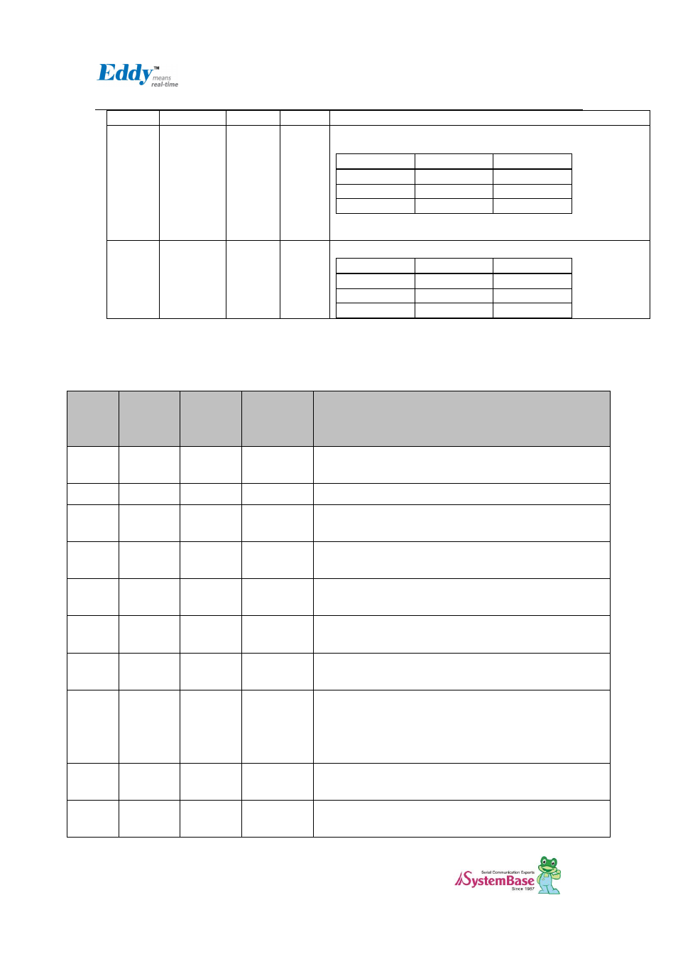
LAN_TX-
J5 pin4
J7 pin4
Ethernet PHY Physical receive or transmit signal (- differential) in CPU
11
LAN_Speed
J5 pin6
J7 pin6
LAN connection status LED
Link/Activity
Pin State
LED Definition
No Link
H
OFF
Link
L
ON
Activity
Toggle
Blinking
12
LAN_Link
J5 pin5
J7 pin5
Link/Activity
Pin State
LED Definition
No Link
H
OFF
Link
L
ON
Activity
Toggle
Blinking
2.5.2.3. Serial (RS232 & COMBO) and PIOA (Peripheral I/O Controller A)
S4M
Pin No
(124)
Name
S4M-JIG
Pin HDR
(46*2)
S4M-DK
Pin HDR
(46*2)
Description
13
P2_RX-
J4 pin20
J6 pin20
COM port #3 Receive differential data negative (Input)
RS422/485 inverting receiver input of Eddy-S4M module
14
RDY#
J4 pin45
J6 pin45
Indicate state of CPU ( normal : blinking)
17
P2_RX+
J4 pin19
J6 pin19
COM port #3 Receive differential data positive (Input)
RS422/485 Noninverting receiver input of Eddy-S4M module
20
DCD0
J4 pin9
J6 pin9
COM port #1 Data Carrier Detection signal
RS232 receiver input of Eddy-S4M module
21
P2_TX+
J4 pin17
J6 pin17
COM port #3 Transmit differential data positive (Output)
RS422/485 Noninverting driver ouput of Eddy-S4M module
22
DTR0
J4 pin7
J6 pin7
COM port #1 Data Terminal Ready signal
RS232 driver output of Eddy-S4M module
25
P2_TX-
J4 pin18
J6 pin18
COM port #3 Transmit differential data negative (Output)
RS422/485 inverting driver ouput of Eddy-S4M module
26
nRESET
J4 pin46
J6 pin46
Reset Input. In S/W, continuously check the interval of ‚LOW‛
when polling input signal from external Reset Key.
Under 5sec : Normal reset function
Over 5sec : Factory Default function
29
P3_RX+
J4 pin23
J6 pin23
COM port #4 Receive differential data negative (Input)
RS422/485 Noninverting receiver input in Eddy-S4M module
30
RxD0#
J4 pin4
J6 pin4
COM port #1 Receive Data signal
RS232 receiver input in Eddy-S4M module