Sw1~sw16: key pad, Sw17: power – Solvline Eddy DKV2.1.0.3 User Manual
Page 29
Chapter 3. Development
Environment
29
2
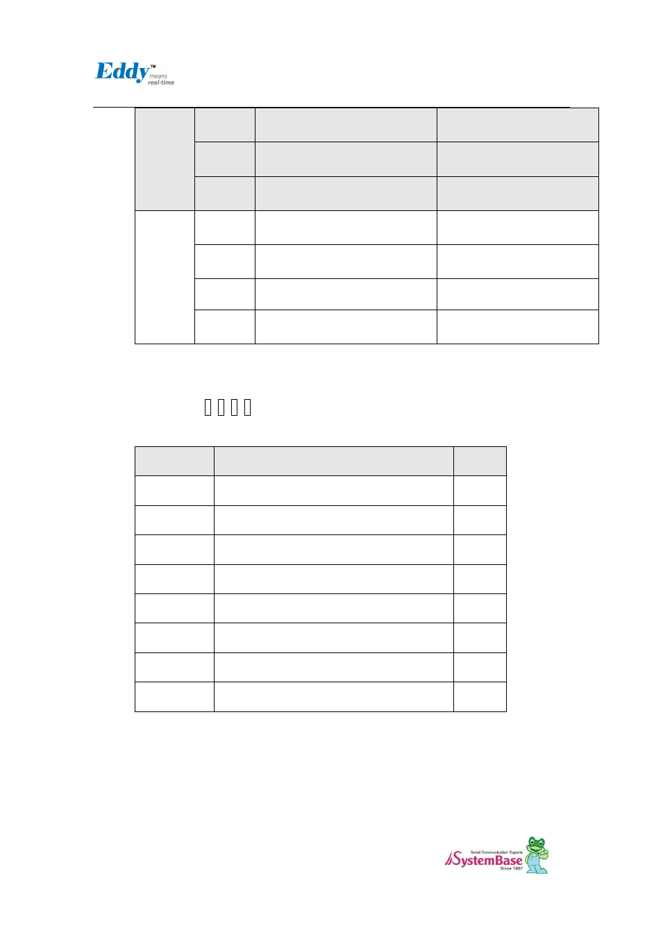
RS422(RX enabled)
RS485 echo-mode
RS485 non echo-mode
3
RS422 Termination Resistor
not connected
RS422 Termination Resistor
Connected
4
RS485 Termination Resistor
not connected
RS422 Termination Resistor
Connected
S9
Port#4
1
RS485 Half-Duplex mode
RS422 Full-Duplex mode
2
RS422(RX enabled)
RS485 echo-mode
RS485 non echo-mode
3
RS422 Termination Resistor
not connected
RS422 Termination Resistor
Connected
4
RS485 Termination Resistor
not connected
RS422 Termination Resistor
Connected
2.4.2.6. SW1~SW16: Key Pad
Key Pad of DK board are consisted with the 4x4 matrix. GPIOs are set to Input mode to read the Key
value. and Key 2, 4, 6, 8 also have the ▲(UP), ▼(DN), ◀(LEFT), ▶(RIGHT) direction function for
LCD menu.
P10-P17
4x4 Key matrix
I/O
PB20
First Row line
IN
PB21
Second Row line
IN
PB30
Third Row line
IN
PB31
Forth Row line
IN
PC20
First Column line from left
IN
PC21
Second Column line from left
IN
PC22
Third Column line from left
IN
PC23
Fourth Column line from left
IN
2.4.2.7. SW17: Power
In order to power up, pull up this switch.