Power, ready led, Debug port led – Solvline Eddy DKV2.1.0.3 User Manual
Page 31
Chapter 3. Development
Environment
31
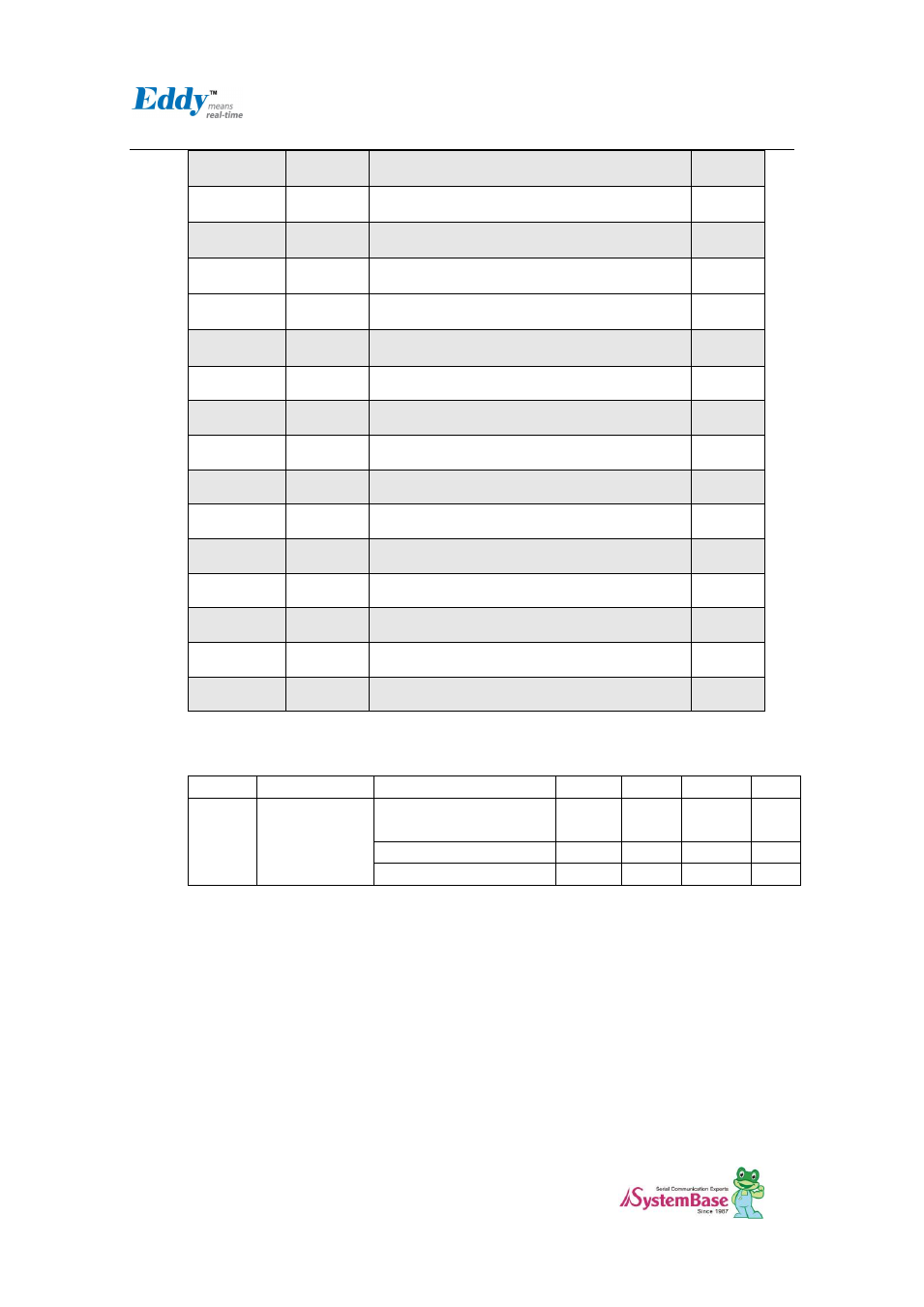
PA5
CTS2
UART #2 Cleat to Send
I
PA4
RTS2
UART #2 Request to Send
O
PB9
RXD2
UART #2 Receive Data
I
PB8
TXD2
UART #2 Transmit Data
O
PB29
CTS1
UART #1 Cleat to Send
I
PB28
RTS1
UART #1 Request to Send
O
PB7
RXD1
UART #1 Receive Data
I
PB6
TXD1
UART #1 Transmit Data
O
PB25
RI0
UART #0 Ring Indicator
I
PB23
DCD0
UART #0 Data Carrier Detection
I
PB22
DSR
UART #0 Data Set Ready
O
PB24
DTR0
UART #0 Data Terminal Ready
I
PB27
CTS0
UART #0 Clear to Send
I
PB26
RTS0
UART #0 Request to Send
O
PB5
RXD0
UART #0 Receive Data
I
PB4
TXD0
UART #0 Transmit Data
O
41.2 DC Characteristics
Symbol
Parameter
Conditions
Min
Typ
Max
Units
Io
Output Current
PA0-PA31 PB0-PB31
PC0-PC3
16
PC4 - PC31 in 3.3V range
2*
mA
PC4 - PC31 in 1.8V range
4
* Eddy DK v2.1 has 3.3V range, so PC4-PC31 PIO is set to 2mA.
(Refer to CPU Datasheet의 41.2 DC characteristics )
2.4.3.2. Power, Ready LED
System Ready (RDY): Indicates that the system is operating normally. (Normal: LED blinks)
Power (PWR): Indicates that the 5 V power is being supplied. (Supplying power: Red LED ON)
2.4.3.3. Debug Port LED
DTXD (Debug Port Transmit Dta LED) : Shows transmission status of the Debug Port.
DRXD (Debug Port Receive Data LED) : Shows reception status of the Debug Port.