S6: nand flash & data flash chip select, S7:uart select – Solvline Eddy DKV2.1.0.3 User Manual
Page 27
Chapter 3. Development
Environment
27
PC1
ADC1
Lux. Sensor Input(BH1600), RN: U26
IN
PC2
ADC2
Temp. Sensor Input(TMP300), RN: U24
IN
PC3
ADC3
N/A
IN
* RN = Reference Number
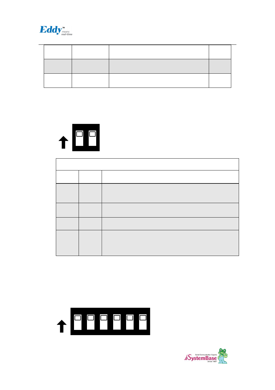
2.4.2.3. S6: NAND Flash & Data Flash Chip Select
This switch is Nand Flash & Data Flash Chip select switch. This switch is needed in firmware
Programming.
ON
ON
1
2
Flash Programming & Booting device Selection
Switch
No 1
Switch
No 2
Operation descriotion
OFF
OFF
For Flash Programming
This setting is needed in firmware Programming. refer to 9.2 System
recovery via USB
OFF
ON
Boot from Data Flash.
ON
OFF
Boot from Nand Flash
ON
ON
Boot from Data Flash or Nand Flash which have bootloader. if Both
devices have the bootloader, algorithm in CPU select the bootloader
of Data Flash.
(Reference : CPU Datasheet 13 장 AT91SAM9260 Boot Program)
2.4.2.4. S7:UART Select
In order to test Serial Port, UART Select Switches are pulled down. It means that UARTs in CPU are
connected to Serial Port. If switches are pulled up, GPIO Ports are enabled and LEDs are controlled
by GPIO Ports. And if Switch No.6 is pulled up, GPIO ports are connected with the Expansion
Headers.
ON
ON
1
2
3
4
5
6