Internal device description, Eeprom, Lcd module – Solvline Eddy DKV2.1.0.3 User Manual
Page 36
Chapter 3. Development
Environment
36
2.4.5
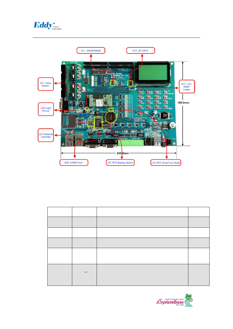
Internal Device Description
2.4.5.1. EEPROM
Eddy-DK v2.1 has the AT25160, 2Kx8bit SPI EEPROM.
2.4.5.2. LCD Module
Graphic LCD Module (PowerTIP PG12864LRU-JCNH11Q and I2C-Bus I/O Expander IC PCA9539)
Signal Name
Function
Description
I/O
P[00:07]
Data bits
Used for data transfer between the CPU and the LCD
module.
I/O
P10
/CS1
Chip enable for D2 (Segment 1 to 64)
IN
P11
/CS2
Chip enable for D3 (Segment 65 to 128)
IN
P12
R/W
R/W signal input is used to select the read /write
mode
High = Read mode, Low = Write mode
IN
P13
D/ I
Register selection input
High = Data register
Low = Instruction register (for write)
Busy flag address counter (for read)
IN