S8:com3 & s9: com4 select – Solvline Eddy DKV2.1.0.3 User Manual
Page 28
Chapter 3. Development
Environment
28
Serial Port & LED
Switch
Bank
Switch
No
Down Position(OFF)
Serial Port Test
UP Position(ON)
GPIO TEST (High : LED On)
S7
1
UART#0 TEST
UART#0 의 TXD, RXD, RTS, CTS
signals are connected with UART#0
RS232 driver IC.
GPIO (PB4, PB5, PB26, PB27) ports are
connected with the GPIO LED of DK
board and disconnected with the
UART#0 RS232 driver IC.
2
UART#0 TEST
UART#0 의 DTR, DSR, DCD, RI signals
are connected with UART#0 RS232
driver IC.
GPIO (PB24, PB22, PB23, PB25) ports
are connected with the GPIO LED of DK
board and disconnected with the
UART#0 RS232 driver IC.
3
UART#1 TEST
UART#1 의 TXD, RXD, RTS, CTS
signals are connected with UART#1
RS232 driver IC.
GPIO (PB6, PB7, PB28, PB29) ports are
connected with the GPIO LED of DK
board and disconnected with the
UART#1 RS232 driver IC.
4
UART#2 TEST
UART#2 의 TXD, RXD, RTS, CTS
signals are connected with UART#2
RS422/485 driver IC.
GPIO (PB8, PB9, PA4, PA5) ports are
connected with the GPIO LED of DK
board and disconnected with the
UART#2 RS422/485 driver IC.
5
UART#3 TEST
UART#3 의 TXD, RXD, RTS, CTS
signals are connected with UART#3
RS422/485 driver IC.
GPIO (PB10, PB11, PC8, PC10) ports
are connected with the GPIO LED of DK
board and disconnected with the
UART#3 RS422/485 driver IC.
6
For Serial Port & GPIO Test
Serial Port and GPIO LED of DK board
are enabled.
Connect to Expansion Header
UART#0~#3 and GPIO LEDs are
disconnected with the Eddy-CPU board
and directly connected with the
Expansion Header(J2, J4)
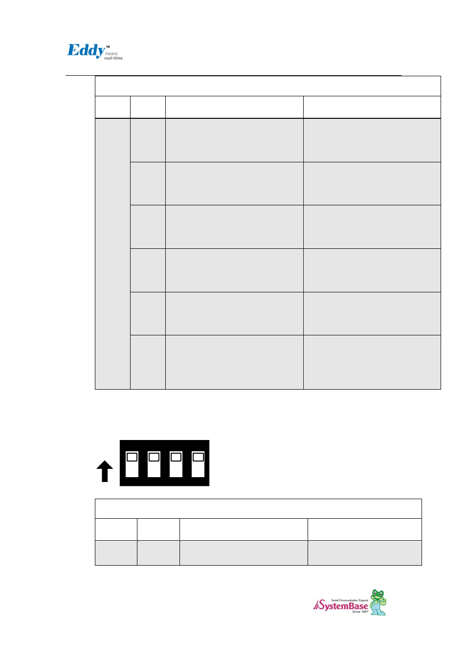
2.4.2.5. S8:COM3 & S9: COM4 Select
COM Port #3 and COM Port #4 set the RS422/RS485 mode.
ON
ON
1
2
3
4
COM PORT#3, #4 settings
Switch
Bank
Switch
No
Down Position(OFF)
UP Position(ON)
S8
Port#3
1
RS485 Half-Duplex mode
RS422 Full-Duplex mode