About the kit, Before setting unit on the curb, Warning – Reznor R8HE Unit Installation Manual User Manual
Page 47: Important notice to installer
47
APPENDIX B - HEAT EXCHANGER CONDENSATE DRAIN & VENT KIT
(ROOF CURB MOUNT APPLICATIONS)
WARNING:
ELECTRICAL SHOCK, FIRE OR
EXPLOSION HAZARD
Failure to follow safety warnings exactly could
result in serious injury or property damage.
Improper servicing could result in dangerous
operation, serious injury, death or property
damage.
• Before servicing, disconnect all electrical power
to the equipment.
• When servicing controls, label all wires prior
to disconnecting. Reconnect wires correctly.
• Verify proper operation after servicing.
About the Kit
This accessory kit is for use with 2-5 Ton 95% condensing
style package gas/electric unit roof curb mount installations
for proper heat exchanger condensate disposal and
venting.
is a detailed listing of the components
in the drain and vent kit to allow the heat exchanger
condensate line to pass through the roof. Please check
the contents of the kit with that of the parts listing, and
familiarize yourself with each component.
Before Setting unit on the Curb
IMPORTANT NOTICE TO INSTALLER
When setting the roof curb for installation, routing
and securement of the gas heat exchanger
condensate drain line must be determined and
installed prior to setting the unit on the curb.
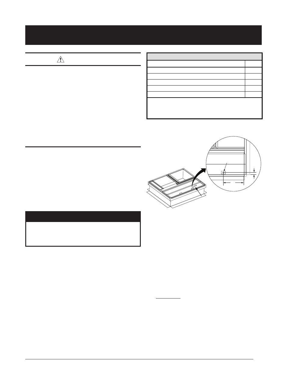
• Nordyne Condensate Drain & Vent Kit # 922485 is set
up for installing the HX condensate drain line straight
down through the roof. It is recommended to drill a
1.00”-1.25” diameter hole through the roof below the
rectangular opening located in outer close off curb panel
(G) of Nordyne offered curbs, approximately 15” in from
the short side of curb and 1”-2” in from the long side of
curb. See
.
• If drilling a hole is not an option, routing the condensate
drain hose over to the duct passage opening with enough
slope is acceptable as long as drain line is secured
to curb and duct, ensuring no kinks or traps can form
between the collector box drain or interior of the building.
Leave a minimum of 24” drain line extending out the
top of roof curb front close off panel (G) for passage
through unit bottom and connection to unit drain when
unit is being set. See
as required.
• It is recommended no non-serviceable connections are
introduced in the drain line between unit drain connection
and an accessible area within the building interior.
Securement of the drain line to the inside surface of
the roof curb is acceptable and should be made in the
wood nailer area (top 3.5”) to avoid possible leaks or
penetrations to roofing materials.
• Cut and remove the insulation covering the 2” x 3”
condensate drain passage in outer panel (G) only.
Before installing inner panel (G) make sure there is
enough slope and there are no kinks or high spots
that could trap water in the line prior to entering the
warmer interior of the building where a drain trap
is REQUIRED.
KIT SUPPLIED PARTS
DESCRIPTION
QTY
2” pvC
x
22.5 d
eGree
e
lbow
& 1/4” m
esh
s
Creen
1
s
prinG
h
ose
C
lamp
1
1/2” id
x
84” d
rain
h
ose
1
h
ose
C
lamp
3/4” d
iameter
1
s
elf
t
appinG
s
Crews
1
FIELD SUPPLIED PARTS
• PVC Solvent Cleaner and Pipe Cement.
• Additional condensate drain components to complete the
installation: PVC Pipe, Hose Clamps, Hangers.
Table 21. Kit and Field Supplied Parts
24” MINIMUM OF 1/2” I.D. TUBING
REQUIRED OUTSIDE OF ROOF
CURB TOP (R8HE MODELS ONLY)
1” - 2”
15”
1” to 1.25” Dia.
Through Roof
(G)
Figure 24. Roof Curb for 2 - 5 Ton Units