Unbalanced 3-phase supply voltage, Thermostat / low voltage connections, Stage heat / 1-stage cool thermostat – Reznor R8HE Unit Installation Manual User Manual
Page 12: Single stage heat / single stage cool thermostat
12
• All 208-240 volt units are shipped from the factory wired
for 240 volt transformer operation. For 208V operation,
remove the lead from the transformer terminal marked
240V and connect it to the terminal marked 208V.
• Connect the line-voltage leads to the terminals on the
contactor inside the control compartment.
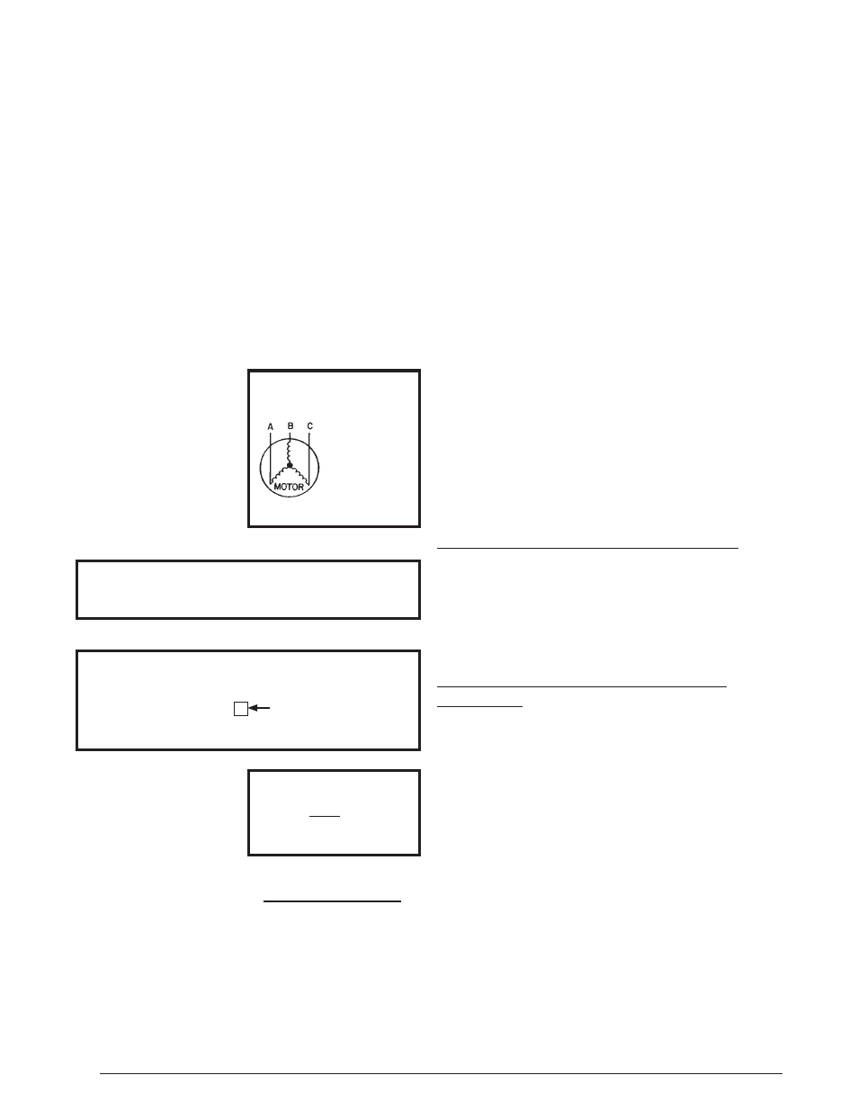
Unbalanced 3-Phase Supply Voltage
Voltage unbalance occurs when the voltages of all phases
of a 3-phase power supply are no longer equal. This
unbalance reduces motor efficiency and performance.
Some underlying causes of voltage unbalance may
include: Lack of symmetry in transmission lines, large
single-phase loads, and unbalanced or overloaded
transformers. A motor should never be operated when a
phase imbalance in supply is greater than 2%.
Perform the following steps to determine the percentage
of voltage imbalance:
1. Measure the line voltages
of your 3-phase power
supply where it enters
the building and at a
location that will only
be dedicated to the
unit installation. (at the
units circuit protection or
disconnect).
EXAMPLE:
AB = 451V
BC = 460V
AC = 453V
2. Determine the average voltage in the power supply.
In this example, the measured line voltages were 451,
460, and 453. The average would be 454 volts (451 +
460 + 453 = 1,364 / 3 = 454).
3. Determine the maximum deviation:
EXAMPLE
From the values given in step 1, the BC voltage (460V)
is the greatest difference in value from the average:
460 - 454 = 6
454 - 451 = 3
454 - 453 = 1
4. Determine percent of
voltage imbalance by
using the results from
steps 2 & 3 in the following
equation.
6
454
100 x
= 1.32%
EXAMPLE
max voltage deviation
from average voltage
= 100 x
average voltage
% Voltage Imbalance
The amount of phase imbalance (1.32%) is satisfactory
since the amount is lower than the maximum allowable
2%. Please contact your local electric utility company if
your voltage imbalance is more than 2%.
Highest Value
Thermostat / Low Voltage Connections
• This unit is designed to operate from a 24 VAC Class II
control circuit. A single stage cooling / two stage heating
thermostat should be used with this unit. See
for typical thermostat connection.
• The control circuit wiring must comply with the current
provisions of the NEC (ANSI/NFPA 70) and with
applicable local codes having jurisdiction. Thermostat
connections should be made in accordance with the
instructions supplied with the thermostat and the indoor
equipment.
• The low voltage wires must be properly connected.
Route 24V control wires through the sealing grommet
near the power entrance. Recommended wire gauge
and wire lengths for typical thermostat connections are
listed in
.
• Several thermostat options are available depending
on the accessories installed with the unit. Select a
thermostat that operates in conjunction with the installed
accessories.
• The thermostat should be mounted about 5 feet above
the floor on an inside wall. DO NOT install the thermostat
on an outside wall or any other location where its
operation may be adversely affected by radiant heat from
fireplaces, sunlight, or lighting fixtures, and convective
heat from warm air registers or electrical appliances.
Refer to the thermostat manufacturer’s instruction sheet
for detailed mounting information.
2-Stage Heat / 1-Stage Cool Thermostat
(Recommended): For highest efficiency a 2 Stage Heating/
Single Cooling thermostat is recommended for this unit. A
Single Stage Cool thermostat is only required for cooling
operation control of this unit. A 2 Stage Heat thermostat
will allow the gas heat to operate at a more efficient low
heat condition until there is a demand for higher heat
output to the conditioned space.
Single Stage Heat / Single Stage Cool
Thermostat
(Optional): A Single Stage Cool thermostat is only required
for cooling operation of this unit. A Single Stage Heat
thermostat can be used in conjunction with the automatic
heat staging jumper on the ignition control board. The heat
staging function will automatically move the unit into high
heat operation after 10 minutes when the jumper is moved
from OFF to the ON position. See
.
Connect the Red, Yellow, Green, White, and Brown low
voltage thermostat wires to terminals
R, Y1 (1st Stage
Cool),
G, W1 (1st Stage Heat), & W2 2nd Stage Heat-
optional) on both the thermostat sub-base and unit low
voltage terminal board. The
C terminal (Black wire), is the
24V common wire required on some thermostat models.
See