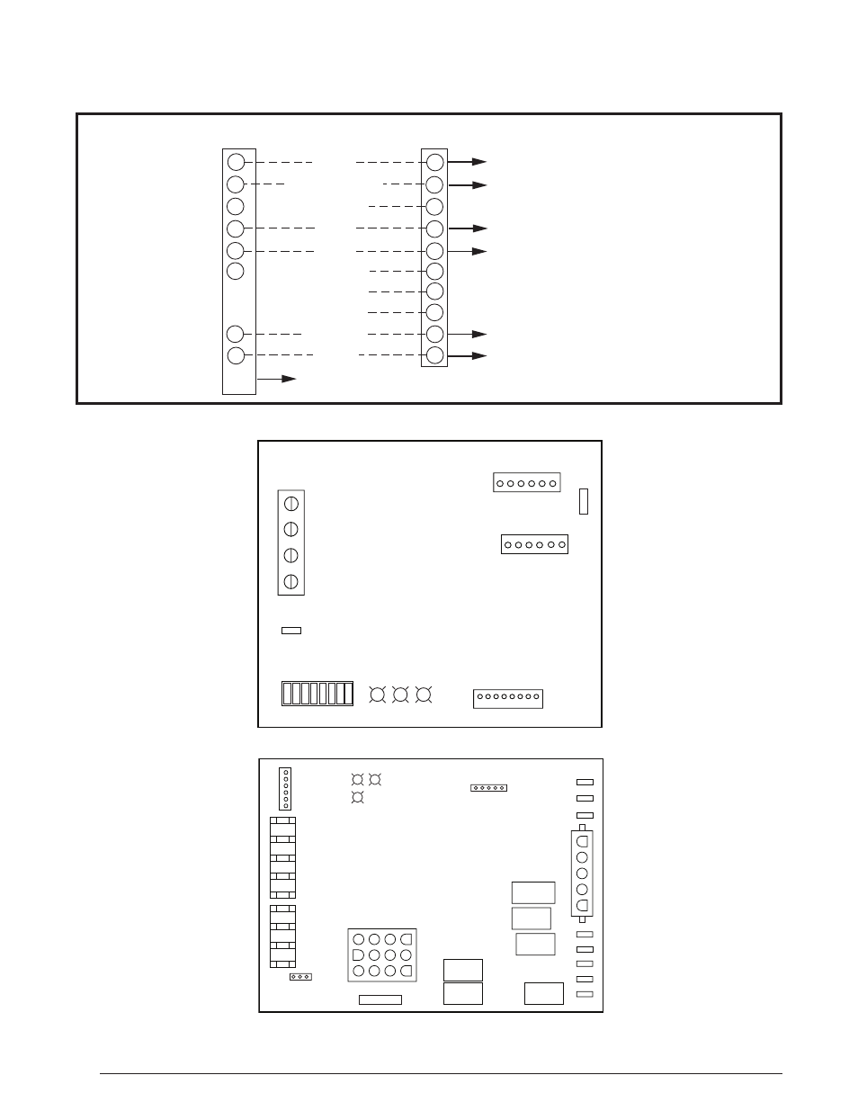
Electrical diagrams, Configuration, Figure 11. fixed speed motor control board – Reznor R8HE Unit Installation Manual User Manual
Page 36: Figure 12. ignition control board - 624817, Figure 10, And thermostat sub-base. see, For switch, 6, 7, & 8 on the motor control board, Home is. see
36
GREEN
RED
STATUS
NO
T USED
TEST PORT
BLOWER MOTOR
R
C
Y1
TWIN
DEHUM
W1
EXPANSION
PORT
COOL
HEAT
FAN SPEED
1 2 3 4 5 6 7 8
OFF ON
Figure 11. Fixed Speed Motor Control Board
LINE- N
XMFR-N
LINE
LINE
XMFR
EAC
HUM
LINE- N
R
C
Y/Y2
W2
G
W1
Y1
GREEN
OFF
EXP
ANSION
POR
T
60
RED
STATUS
90 120 180
YELLO
W
AU
TO
ST
AG
E
BLO
WER
OFF
DELA
Y
THERMOS
TAT
CONNECTIONS
NEUTRALS
(FLAME)
3 AMP FUSE
INPUTS
ON
Figure 12. Ignition Control Board - 624817
Figure 10. Two Stage Heating / Single Stage Cooling Configuration
TERMINAL STRIP
THERMOSTAT
R
G
C
W2
W1
RED
YELLOW
GREEN
BLACK (Optional)
WHITE
C
L
R
W1
G
Y2
Y1
Y1
Y2
W2
BROWN
L
O
E
NOT USED
NOT USED
Blower (Auto or Continuous ON)
24VAC (Common)
1
ST
Stage Heat
24VAC
To Blower Control Board (Optional)
1
ST
Stage Cool
2
ND
Stage Heat
DEHUM
NOT USED
NOT USED
Electrical Diagrams
See also other documents in the category Reznor Radiators:
- UDAP Unit Installation Manual (40 pages)
- UDBP Unit Installation Manual (44 pages)
- UEAS Unit Installation Manual (44 pages)
- VPS Unit Installation Manual (44 pages)
- VPT Unit Installation Manual (40 pages)
- VCS Unit Installation Manual (48 pages)
- CAUA Unit Installation Manual (44 pages)
- EEDU Unit Installation Manual (32 pages)
- LDAP Unit Installation Manual (44 pages)
- MASA Unit Installation Manual (40 pages)
- RDF Unit Installation Manual (28 pages)
- RPB Unit Installation Manual (40 pages)
- SC Duct Furnace Unit Installation Manual (40 pages)
- SSCBL Unit Installation Manual (60 pages)
- X Unit Installation Manual (32 pages)
- ZQYRA Unit Installation Manual (72 pages)
- ADF Unit Installation Manual (28 pages)
- F Unit Installation Manual (40 pages)
- PDH (Indoor PreevA) Unit Installation Manual (72 pages)
- MAPSIII Unit Installation Manual (76 pages)
- RDH (Outdoor PreevA) Unit Installation Manual (68 pages)
- RP (Outdoor Duct Furnaces) Unit Installation Manual (32 pages)
- YDHA Unit Installation Manual (76 pages)
- OH Unit Installation Manual (28 pages)
- RBL (Cabinet Blower) Unit Installation Manual (12 pages)
- REC (Evaporative Cooling) Unit Installation Manual (12 pages)
- RIHN Unit Installation Manual (20 pages)
- UDAP Option - Installation - Power Venting (12 pages)
- UDAS Option - Installation - Separated Combustion Venting (16 pages)
- WS Unit Installation Manual (15 pages)
- EBHB Option - Installation - Thermostat Kit (2 pages)
- EFMA Unit Installation Manual (27 pages)
- EWHB Unit Installation Manual (9 pages)
- EXUB Unit Installation Manual (16 pages)
- XAWS Unit Installation Manual (12 pages)
- XAWU Unit Installation Manual (12 pages)
- XBWU Unit Installation Manual (12 pages)
- MAPS III Option - Installation - Energy Recovery Module Installation (12 pages)
- UDAP in sizes 30 through 125 Option - Installation - Ceiling Suspension Kit (2 pages)
- UEAS Option - Installation - Downturn Nozzles - V3 (4 pages)
- UDBP Option - Installation - Polytube Adapter Instructions (4 pages)
- UDBS Option - Installation - Vertical Louvers - V3 Series (2 pages)
- B Option - Installation - Blower/Filter Cabinet (4 pages)
- PDH with 1-stage gas control or 2-stage gas control Gas Conversion Kit Instructions (8 pages)
- VP series infrared heaters High altitude conversion instructions (12 pages)