Cleaning of burners, Replacement parts troubleshooting, Cooling mode – Reznor R8HE Unit Installation Manual User Manual
Page 25: Heating mode, Caution, Replacement parts, Troubleshooting cooling mode
25
Cleaning of Burners
If the burners must be cleaned, follow the steps below.
1. Shut off the gas supply to the unit either at the meter
or at a manual valve in the supply piping.
2. Turn off all power to the unit and set the thermostat to
the lowest temperature setting.
3. Remove the louvered control access panel from the
unit.
4. Turn the gas control switch to the OFF position. See
for gas valve shut off instructions.
5. Disconnect the wires from the gas valve, ignitor, and
flame sensor.
NOTE: Mark wires to prevent miswiring
of unit when reassembling.
CAUTION:
To prevent damage to the unit or internal
components, it is recommended that two
wrenches be used when loosening or tightening
nuts. Do not over tighten!
6. Using two wrenches, separate the ground-joint union
in the gas supply piping at the unit.
7. Remove the piping between the gas valve and the
ground-joint union (if applicable).
8. Remove all screws securing the burner assembly to
the unit.
9. Carefully remove the burner assembly from the unit.
DO NOT DAMAGE THE IGNITER WHILE REMOVING
THE BURNER ASSEMBLY.
10. Inspect the burners for accumulated dust or debris.
If necessary carefully clean them with a soft wire
brush and a vacuum cleaner.
DO NOT DAMAGE THE
IGNITER WHILE CLEANING THE BURNER.
11. Replace all the parts in reverse order from which they
were removed.
12. Follow the lighting instructions found on the lower unit
door to return the unit to operation.
13. Verify proper operation after servicing.
REPLACEMENT PARTS
Replacement parts are available through all Nordyne
distributors. Please have the complete model and serial
number of the unit when ordering replacement parts.
ELECTRICAL:
• Blower Control Board
• Ignitors/Flame Sensors
• Capacitors
• Pressure Switches
• Compressors
• Relays
• Contactors
• Temperature Limit Switches
• Gas Valves
• Thermostats
• Hall Effect Sensor
• Time Delay Relays
• Ignition Controls
• Transformers
MOTORS:
• Blower Motor
• Fan Motor
• Inducer Blower Motor
COMPONENTS:
• Blower Assembly
• Fan Grille
• Burner Manifold
• Filter/Driers
• Burners/Orifices
• Gaskets
• Cabinet Panels
• Heat Exchanger
• Expansion Valves
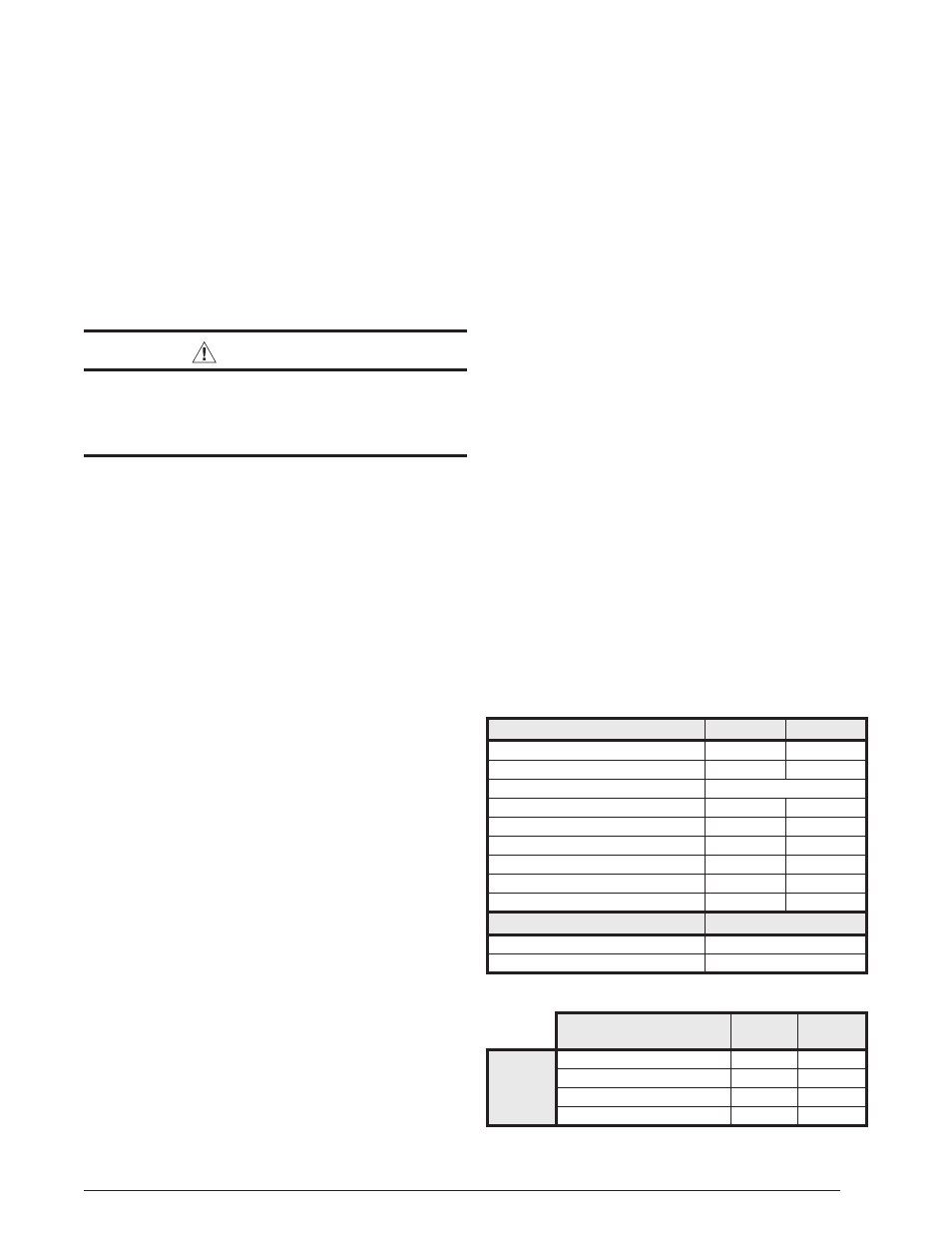
Table 5. Furnace Control Board Fault Conditions
DIAGNOSTIC DESCRIPTION
GREEN LED
RED LED
Control Fault (No Power)
Off
Off
L1/Neutral Polarity Fault
Flash
Flash
1 Hour Lockout
Alternating Flash
Normal Operation
On
On
Pressure Switch Closed Fault
On
Flash
Pressure Switch Open Fault
Flash
On
Open Limit Switch Fault
Flash
Off
Motor Fault
On
Off
Blocked Condensate Drain or Vent
OFF
Flash
DIAGNOSTIC DESCRIPTION
YELLOW LED
Low Flame Sensor Signal
Continuous Flash
Flame Present
On
DIAGNOSTIC
DESCRIPTION
GREEN
LED
RED
LED
VARIABLE
SPEED
FURNACES
Control Fault (No Power)
Off
Off
Normal Operation
On
On
Motor Fault
On
Flash
Communications Fault
Flash
Flash
Table 6. Motor Control Board Fault Conditions
TROUBLESHOOTING
Cooling Mode
If the unit does not operate in the cooling mode, check
the following:
• Verify the thermostat is operating properly
• Verify electrical power to the unit is turned on
• Verify the filters are not dirty
• Verify the service doors are in place
• Verify the 3 amp fuse is operational
• Verify the anti-short cycle timer’s 5 minute cycle has
finished.
• Verify the LED flash code (on the blower control board)
against the diagnostic codes listed in
.
Heating Mode
If the unit does not operate in the heating mode, check
the following:
• Verify the thermostat is operating properly
• Verify electrical power to the unit is turned on
• Verify the filters are not dirty
• Verify the gas is turned on and the manual shut-off valve
is open and the gas valve switch is in the ON position
• Verify the service doors are in place
• Verify the flame roll-out switch is closed
• Verify the 3 amp fuse is operational
• Verify the LED flash codes on the furnace ignition control
board against the diagnostic codes listed in
on the wiring diagrams:
,
• Verify the LED flash codes on the motor control board
against the diagnostic codes listed in
,
, &