Measuring the manifold pressure, Adjusting the manifold pressure, Removing the manometer/pressure gauge – Reznor R8HE Unit Installation Manual User Manual
Page 20: Verifying over-temperature limit control operation, The manifold section, Conversion to lp/propane (sea level and, Figure
20
unit data label. To determine the firing rate, follow the
steps below:
1. Obtain the gas heating value (HHV) from the gas supplier.
2. Shut off all other gas fired appliances.
3. Start the unit in LOW heating mode and allow it to run
for at least 3 minutes.
4. Measure the time (in seconds) required for the gas
meter to complete one revolution.
5. Convert the time per revolution to cubic feet of gas per
.
6.Multiply the gas flow rate in cubic feet per hour by the
heating value of the gas in Btu per cubic foot to obtain
the firing rate in Btu per hour. See
.
EXAMPLE
(INPUT --> HIGH = 100,000 / LOW = 65,000)
• Time for 1 revolution of a gas meter with a 1 cubic foot dial
= 58 seconds.
, read 62 cubic feet gas per hour.
• Local heating value of the gas (obtained from gas supplier)
= 1,040 Btu per cubic foot.
• Low Input rate = 1,040 x 62 = 64,480 Btuh = PASS
7. Record your findings and move unit operation to HIGH
heating mode and Repeat Steps 3-6.
8. Adjust the manifold pressure if necessary by following
the steps in the Measuring & Adusting the Manifold
sections. For additional information about elevations
above 2,000 feet, see High Altitude Conversion section
(
).
Measuring the Manifold Pressure
The manifold pressure must be measured for both LOW
and HIGH fire by installing a pressure gauge (Manometer,
Magnehelic Meter, etc.) to the outlet end of the gas valve
as follows:
1. Turn off all electrical power to the appliance.
2. Shut OFF the gas supply at the manual shutoff valve
located outside of the appliance.
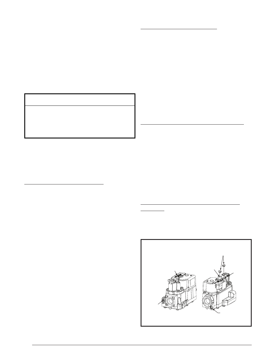
3. Using a 3/16” Allen wrench, remove the manifold
pressure tap plug located on the outlet side of the gas
valve (
).
4. Install an 1/8” NPT pipe thread fitting, that is compatible
with a Manometer or similar pressure gauge.
5. Connect the Manometer or pressure gauge to the
manifold pressure tap.
6. Set the room thermostat 1 degree above room
temperature To start the furnace on LOW fire.
7. Allow the furnace to operate for 3 minutes and then
check the manifold pressure. Compare the measured
value with the value shown in
for
Natural Gas and
for LP/Propane
gas. If the manifold pressure is not set to the appropriate
pressure, then it must be adjusted.
8. Record your findings and move unit operation to HIGH
heating mode and Repeat Steps 3-6.
Adjusting the Manifold Pressure
NOTE: If adjustment must be made to either LOW or
HIGH fire settings perform the following steps:
1. Remove the cap screw from the top of the gas valve
regulator (
).
2. Using a screwdriver or Allen wrench (where appropriate),
slowly turn the adjustment screw till the appropriate
manifold pressure listed in
, or the
LOW and/or HIGH firing rate for your specific gas HHV
is achieved.
NOTE: Turning the screw clockwise increases the
pressure, turning the screw counter-clockwise
decreases the pressure. To prevent the screw from
backing all the way out from the valve, turn the screw
slowly.
3. Replace and tighten the cap screw or the plastic cap
over the adjustment screw.
Removing the Manometer/Pressure Gauge
After the LOW and HIGH manifold pressures are properly
adjusted, the Manometer or pressure gauge must be
removed from the gas valve.
1. Turn the thermostat to its lowest setting.
2. Turn OFF the main gas supply to the unit at the manual
shut-off valve, which is located outside of the unit.
3. Turn OFF all of the electrical power supplies to the unit.
4. Remove the pressure gauge adapter from the gas valve
and replace it with the 1/8” NPT manifold pressure plug
that had been removed earlier.
NOTE: Make sure the
plug is tight and not cross-threaded.
5. Turn ON the electrical power to the unit.
6. Turn ON the main gas supply to the unit at the manual
shut-off valve.
Verifying Over-Temperature Limit Control
Operation
1. Verify the louvered control access panel is in place and
that there is power to the unit.
2. Block the return airflow to the unit by installing a close-
off plate in place of or upstream of the filter.
Inlet
Pressure
Tap
Manifold
pressure
Tap
2-STAGE GAS VALVE
Model VR9205Q1127
ON / OFF
Switch
High Input
Adjusting
Screw
Lo Input
Adjusting
Screw
Cap
Screws
Figure 7. Regulator Capscrew & Tap Locations