About the kit, Vent pipe & drain hose assembly, Vertical drain pit method – Reznor R8HE Unit Installation Manual User Manual
Page 43: Warning
43
APPENDIX A - HEAT EXCHANGER CONDENSATE DRAIN & VENT KIT
(HORIZONTAL MOUNT APPLICATIONS)
WARNING:
ELECTRICAL SHOCK, FIRE OR
EXPLOSION HAZARD
Failure to follow safety warnings exactly could
result in serious injury or property damage.
Improper servicing could result in dangerous
operation, serious injury, death or property
damage.
• Before servicing, disconnect all electrical power
to the equipment.
• When servicing controls, label all wires prior to
disconnecting. Reconnect wires correctly.
• Verify proper operation after servicing.
About the Kit
This Condensate Drain and Vent Kit (P/N 922323) is
available for purchase as an accessory item for R8HE
series condensing style package gas/electric units. These
instructions may be used to properly field install a heat
exchanger condensate disposal and venting system.
is a detailed listing of the components that will be needed
to properly connect the heat exchanger condensate drain
and vent system if the kit is not being used.
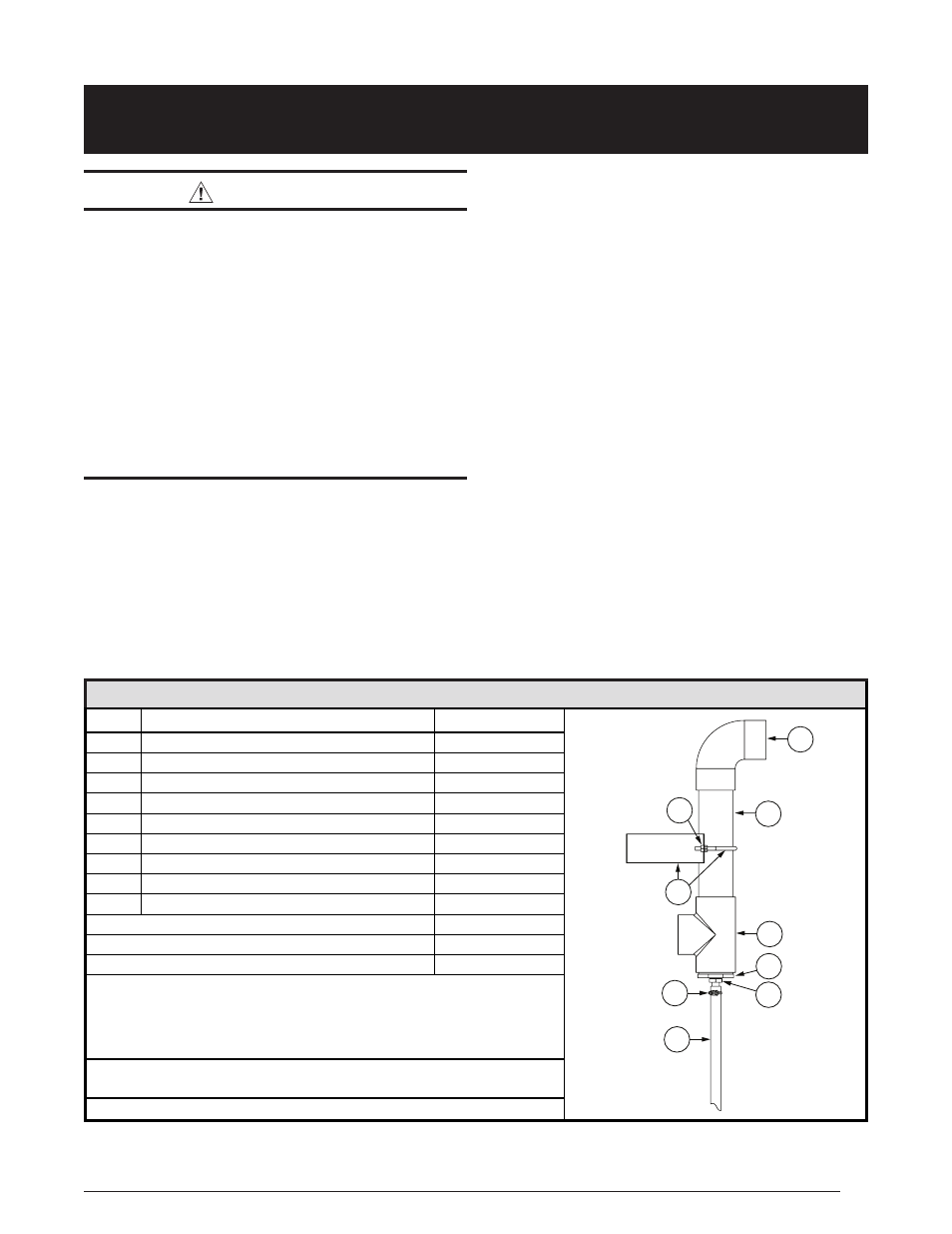
Table 19. Parts List
FIELD SUPPLIED PARTS
ITEM #
DESCRIPTION
QTY
1
2” PVC x 90 Degree Elbow & 1/4” Mesh Screen
1
2
2” PVC x 10” Pipe
1
3
2” PVC Tee
1
4
2” x 1/2” PVC Reducer Bushing
1
5
1/2” Barb x 1/2” NPTF
1
6
Spring Hose Clamp
1
7
1/2” ID x 36” Drain Hose
1
8
Horizontal Vent Support Bracket & U-Bolt
1
9
1/4-20 Nuts
4
Self Drilling Screws (Not shown)
2
Wire Tie (Not shown)
1
3 Ft. Flexible Insulation (Not Shown)
1
2” PVC pipe x Length. (Length is approximately 16” + Regional Frost Line Depth for
unit on standard 2’ concrete pad).
NOTE: For a trench style drain installation (page 3)
you will also need 4”x36” (min.) corrugated flexible pipe w/ drain holes, a 2”x4” PVC
reducer, 4” corrugated piping connection, 2”x90 degree PVC elbow, and 4” filtration
sleeve or permeable barrier material. (Not Shown)
40-80 Lb. Rock or chat, (Limestone rock or lime pellets if required by local code for
neutralizing the condensate when disposing into the ground). (Not Shown)
PVC Solvent Cleaner and Pipe Cement. (Not Shown)
2
1
3
4
5
6
7
8
9
Vent Pipe & Drain Hose Assembly
1. Connect the horizontal 13.25” x 2” PVC pipe (supplied
with the unit) to the inducer motor rubber coupler
and secure using 3” hose clamp provided.
NOTE: A
horizontal pipe length up to 18” is approved if pit location
circumstances require it to be further from the unit and
pad. A new support bracket or adaptor piece will have
to be field created to ensure the vent assembly does
not rotate.
2. Clean & glue the 2” x ½” reducer bushing into the Tee.
3. Install the ½” hose connector to the reducer bushing.
4. Place the 2” PVC Tee onto the end of the horizontal
pipe.
DO NOT CEMENT THE TEE ON AT THIS TIME.
Drop a plumb line from the bottom of the ½” drain fitting
to the ground to locate the starting point of the pit or
trench.
Vertical Drain Pit Method
IMPORTANT NOTE:
The flue condensate of this unit is slightly acidic and
some local codes may require a neutralizing treatment
when disposing directly into the ground. Check state
or local code requirements for application of this
equipment and if necessary substitute limestone
rock, chat, or lime pellets to the pit to neutralize the
condensate instead of using basic rock or chat.