Index – Reznor RPB Unit Installation Manual User Manual
Page 39
Form I-RPB, P/N 131782 R12, Page 39
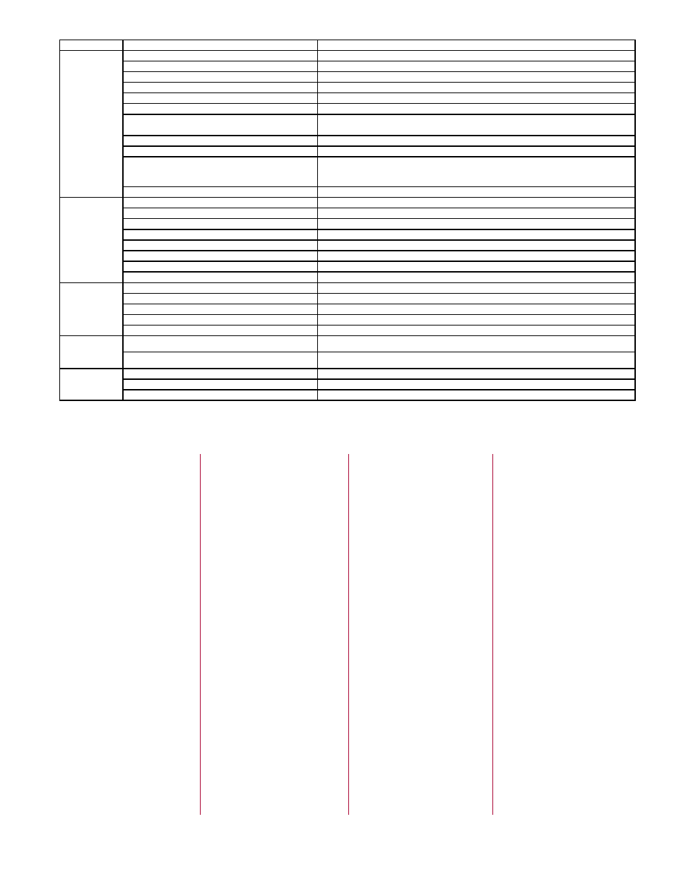
TROUBLE
PROBABLE CAUSE
REMEDY
Pilot lights;
main valve will
not open.
1. Manual valve not open.
1. Open manual valve.
2. Main valve not operating.
2.
a) Defective valve.
a) If 24 volt is measured at valve connections and valve remains closed, replace valve.
b) Loose wire connections.
b) Check and tighten all wiring connections.
3. Ignition control does not power main valve.
3.
a) Loose wire connections.
a) Check and tighten all wiring connections.
b) Flame sensor grounded. (Pilot lights - spark
continues)
b) Be certain flame sensor lead is not grounded or insulation or ceramic is not
cracked. Replace as required.
c) Gas pressure incorrect.
c) Adjust gas pressure. (See Paragraph 6.1.)
d) Cracked ceramic at sensor.
d) Replace sensor.
e) Faulty ignition controller.
e) See Paragraph 8.2. If all checks indicate no other cause, replace ignition controller.
Do not attempt to repair the ignition controller. This device has no field replaceable
parts.
f) Poor microamp signal
f) Adjust pilot regulator
No heat
(Heater
operating.)
1. Dirty filters in blower system.
1. Clean or replace filters.
2. Incorrect manifold pressure or orifices.
2. Check manifold pressure (See Paragraph 6.1).
3. Cycling on limit control.
3. Check air throughput (See Paragraph 6.5).
4. Improper thermostat location or adjustment.
4. See thermostat manufacturer's instructions.
5. Belt slipping on blower
5. Adjust belt tension
6. Fan control improperly wired
6. Connect as per wiring diagram.
7. Defective fan control.
7. Replace fan control.
8. Blower set for too low temperature rise.
8. Slow down blower or increase static pressure.
Motor will not
run
1. Circuit open
1. Check wiring and connections.
2. Fan Control inoperative
2. Replace fan control.
3. Fan control improperly wired
3. Connect as per wiring diagram.
4. Contactor inoperative
4. Replace contactor.
5. Defective motor.
5. Replace motor.
Motor turns on
and off while
operating
1. Motor overload device cycling
1. Check motor load against motor rating place. Replace motor or overload device.
2. 3-phase motor rotating in opposite direction
2. Interchange two legs of supply connections.
Motor cuts out
on overload
1. Improper motor pulley adjustment
1. See instructions on air throughput (See Paragraph 6.5).
2. Improper static pressure on duct system
2. Adjust dampers in duct system.
3. Low voltage
3. Check power supply.
Index
A
Opt High Ambient Limit Control 29
AquaSaver Timed Metering 16
AquaSaver Timer Adjustment 18
B
Belt Tension 22
Blocked Vent Switch 29
Burner Air Adjustment 34
C
Check Installation After Startup 35
Check Installation and Start-Up 34
Cleaning Pilot and Main Burners 37
Cleaning the Heat Exchanger 37, 38
Combustion Air Pressure Switch Setting
with AG39 32
Combustion Air Requirements 3
D
Optional Dampers & Controls 14
Dimensions of Outside Air Hood 11
Discharge Air Sensor 21, 22
E
Electrical Supply & Connections 24
Optional Electronic Modulation 30
Evaporative Cooling Maintenance 18
F
Filter Arrangements 13
Float Valve 16
G
Gas Valve 29, 36
H
Outside Air Hood 11
I
Inlet Air 11
INSTALLATION RECORD 40
L
M
Option AG39 Manifold Arrangement 31
O
Operation of Option AG39 31
P
Pilot and Ignition Systems 33, 34
PRESSURE TESTING SUPPLY
R
Reverse Flow, Limit Control 28
Roof Curb Assembly and Installation 7
S
Supply & Drain Water Connections 15
Supply Air Discharge 20
Combustion air proving switch 29
T
Troubleshooting Evap Cooler 20
Troubleshooting Guides - Opts
Optional Two-Stage Operation 29
U
V
2-Way Valve 16
3-Way Valve 16
Gas Valve 29
Optional Vertical Vent (Opt CC3) 10
Supply Voltage 24
W
Wiring and Service - AG39 32