0 maintenance and service, 1 maintenance schedule, 2 maintenance procedures – Reznor RPB Unit Installation Manual User Manual
Page 36: 1 maintenance schedule 10.2 maintenance procedures
Form I-RPB, P/N 131782 R11, Page 36
WARNING
If you turn off the power supply, turn off the gas. See Hazard Levels,
page 2.
This unit will operate with a minimum of maintenance. To ensure long life and satis-
factory performance, a furnace that is operating under normal conditions should be
inspected every four months. If the furnace is operating in an area where an unusual
amount of dust or soot or other impurities are present in the air, more frequent inspec-
tion is recommended.
The following procedures should be carried out at least annually (See Paragraphs
10.2.1-10.2.4 for instructions).
Inspect the filters. Clean or replace as needed.
Inspect the blower and belt. Check belt for tension, wear and alignment. Adjust or
replace as needed. Clean dirt from blower and motor.
Clean all dirt and grease from the primary and secondary combustion air openings.
Check the gas valve to ensure that gas flow is being shut off completely.
Clean the heat exchanger both internally and externally.
Check the pilot burner and main burners for scale, dust, or lint accumulation.
Clean as needed.
Check the flue products outlet; clean if needed. Check the vent cap in an optional
extended vent system; replace any parts that do not appear sound.
Check the wiring for any damaged wire. Replace damaged wiring. (See Paragraph
7.0 for wiring requirements.)
CAUTION: When cleaning, wearing eye protection is recommended.
10.0 Maintenance
and Service
10.1 Maintenance
Schedule
10.2 Maintenance
Procedures
10.2.1 Gas Valve
WARNING
The operating valve is the prime safety shutoff. All gas supply lines
must be free of dirt or scale before connecting to the unit to ensure
positive closure. See Hazard Levels, page 2.
Remove external dirt accumulation and check wiring connections.
The combination gas valve must be checked annually to ensure that the valve is shut-
ting off gas flow completely.
Instructions:
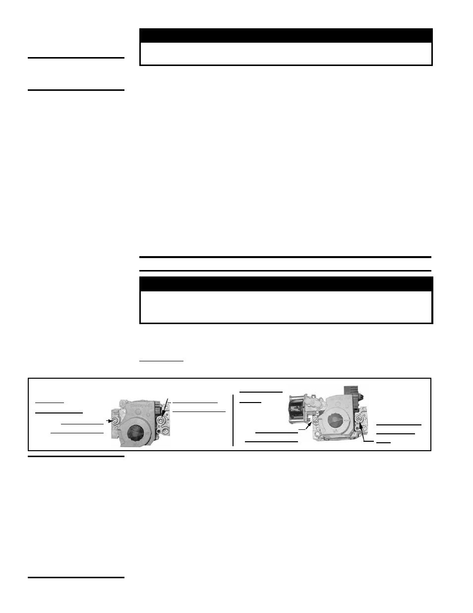
1) Locate the 1/8” FPT INLET pressure tap on the combination valve (FIGURE 37).
NOTE: Use only factory-
authorized replacement
parts.
NOTE: Operational
pressure settings and
instructions for checking
pressure settings are in
Paragraph 6.1.
2) With the manual valve turned off to prevent flow to the gas valve, connect a
manometer to the 1/8” inlet pressure tap in the valve.
NOTE: A manometer (fluid-
filled gauge) with an inches water column scale is recommended.
3) With the field-installed manual valve remaining closed, observe the manometer
for two to three minutes for an indication of gas pressure. No pressure should
be indicated on the manometer.
If the manometer indicates a gas pressure,
the field-installed manual gas valve must be replaced or repaired before the
combination gas valve can be checked.
4) If the manometer does not indicate gas pressure, slowly open the field-installed
manual gas valve. After the manometer's indicated gas pressure has reached
equilibrium, close the manual shutoff valve. Observe the gas pressure. There
should be no loss of gas pressure on the manometer. If the manometer indicates
a loss of pressure, replace the combination gas valve before placing the heater in
operation.
CAUTION: DO NOT
bottom out the gas
valve regulator
adjusting screw.
This can result
in unregulated
manifold pressure
causing excess
overfire and heat
exchanger failure.
Single-
Stage Valve
1/8" INLET
Pressure Tap
1/8” Outlet
Pressure Tap
Two-Stage
Valve
1/8" INLET
Pressure Tap
1/8” Outlet
Pressure
Tap
FIGURE 37 - Top View of Gas Valves