Reznor RPB Unit Installation Manual User Manual
Page 15
Form I-RPB, P/N 131782 R12, Page 15
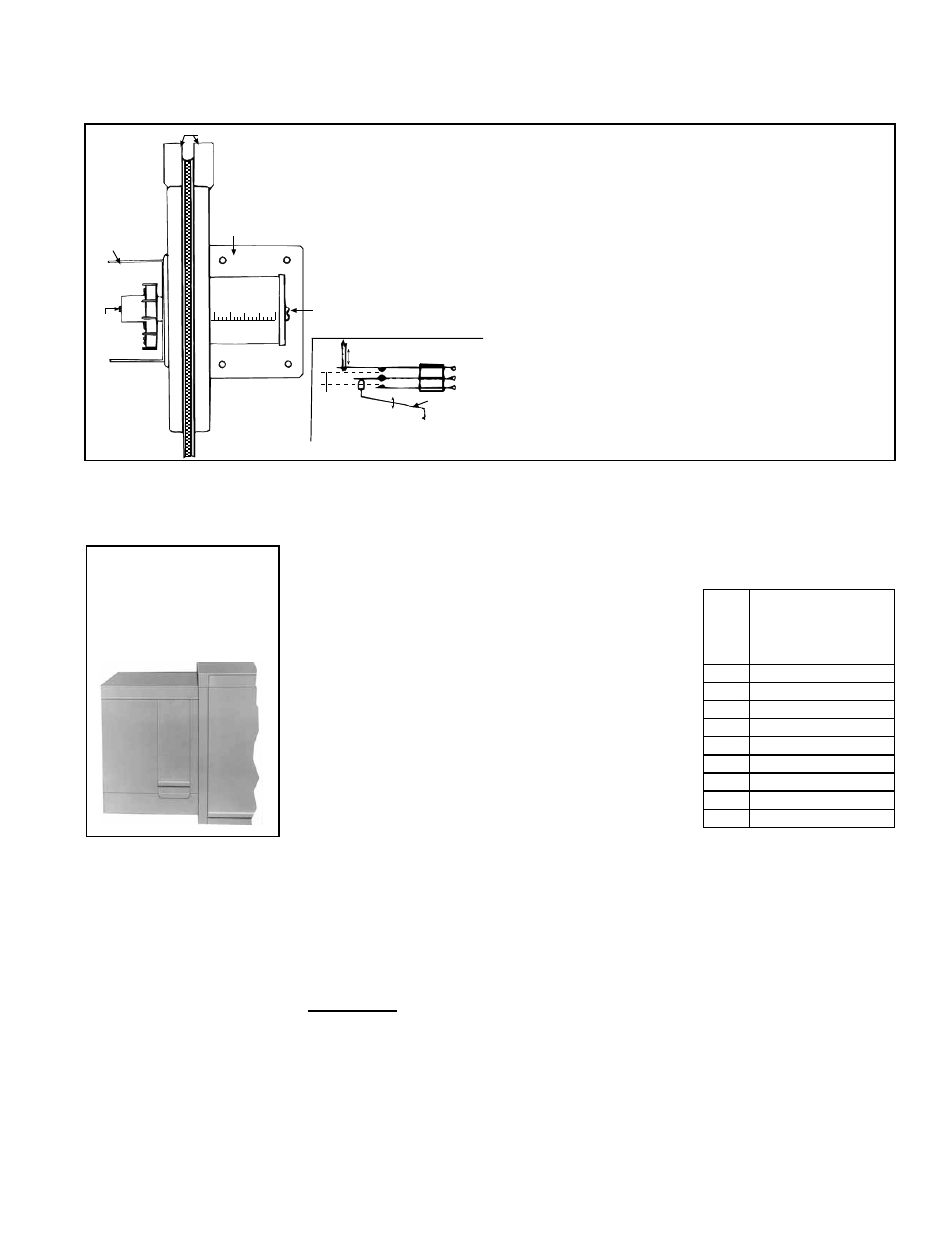
Electric Box
Span
Adjust
Screw
Mounting Plate
Pressure Taps
Low
High
Pressure
Adjust Screw
Increasing
Decreasing
Linkage to
Diaphragm
Low
Common
High
Span Adjustment
Span of
floating
contact
Switching action in the pressure null switch
FIGURE 13 - Pressure Null Switch (used with Inlet Air Option AR23)
IMPORTANT: To eliminate shipping damage to
the switch contacts, the manufacturer reduced
the span adjustment to zero before shipping.
The span should be adjusted prior to using
the switch. (If the switch has been installed,
disconnect the vent tube so that the null switch
is in a neutral position.) Remove the electrical
box cover and while observing the contacts, turn
the span adjustment screw slowly in a clockwise
direction. Continue turning the adjustment screw
until you are able to see gaps between the
common and both the low and high contacts. A
minimum gap provides the greatest sensitivity.
The wider the gap the lower the sensitivity.
Building pressure is set by turning the adjustment screw. The "Low" actuation point
is set by adjusting the span of the null by turning the span adjustment screw. The
span range is .01 to .03" w.c.
5. See the wiring diagram included with the furnace to make electrical connections.
6.3.4 Evaporative
Cooling Module,
Option AS 3, 4, 5, 8
General - Evaporative cooling provides excellent comfort cooling at low initial equip-
ment and installation costs and low operating and maintenance costs. Direct evapo-
rative cooling works solely on the principle that water in direct contact with a moving
airstream will eventually evaporate if the droplets have long enough exposure. This
evaporative cooling module uses wetted rigid cellulose or rigid glass fiber media to
retain water in order to allow time for evaporation.
FIGURE 14 - Optional
Evaporative Cooling
Module is factory-
installed on the
blower cabinet
The optional evaporative cooling module is equipped
with high efficiency pad media of 12" rigid cellulose
(Option AS4) or 12" rigid glass fiber (Option AS8). 12"
media provides 90% efficiency. Efficiency values are
stated at maximum allowable CFM without the addi-
tion of a moisture elimination pad with an inlet dry bulb
temperature of 95°F and inlet wet bulb temperature of
65°F. The evaporative cooling efficiency is a function
of inlet temperature and of face velocity through the
media. The stated cooling efficiency will rise with the
decrease of CFM and the increase of inlet tempera-
ture. Moisture elimination pads (Option ASA1) may be
used on all units but are required on high CFM units as
listed in the table.
The standard water controls for the evaporative cooling module include the float valve,
the float switch, and pump assembly illustrated in the following paragraphs. If the cool-
ing module has an optional AquaSaver
metering water system, it will not have these
controls but will have a solenoid valve with a timer assembly for controlling water flow.
RPB
Size
Moisture Elimina-
tion Pad Required
on Evaporative
Cooling Module
125
2601 - 3800 CFM
150
3201 - 4700 CFM
175
3201 - 5000 CFM
200
3701 - 5100 CFM
225
3701 - 5150 CFM
250
4501 - 5800 CFM
300
4501 - 6300 CFM
350
5101 - 6800 CFM
400
5601 - 7100 CFM
Supply and Drain Water
Connections
Installation Instructions
- Evaporative Cooling
Module
The evaporative cooling module is factory assembled, installed and wired. No addi-
tional roof mounting is necessary. Read the following to field connect the water supply
and make necessary checks and adjustments before operating the cooling module.
Float Valve (FIGURE 15)
In a module with pump and float controls, a float valve maintains the appropriate water
level in the reservoir.
Use a field-supplied 1/4" diameter tubing with a compression nut and tubing ferrule to
connect the fresh water supply to the inlet of the float valve. See
FIGURE 15. Place nut
and ferrule over tubing and insert tubing into the float valve stem. Tighten nut securely.
An optional automatic fill and drain kit (Option CT) is available that will automatically
release supply water to the cooling module when a call for cooling is made and drain
all water from the reservoir when the cooling switch is deactivated or a cooling ther-