0 mechanical (cont'd), 3 unit inlet air (cont'd) – Reznor RPB Unit Installation Manual User Manual
Page 12
Form I-RPB, P/N 131782 R11, Page 12
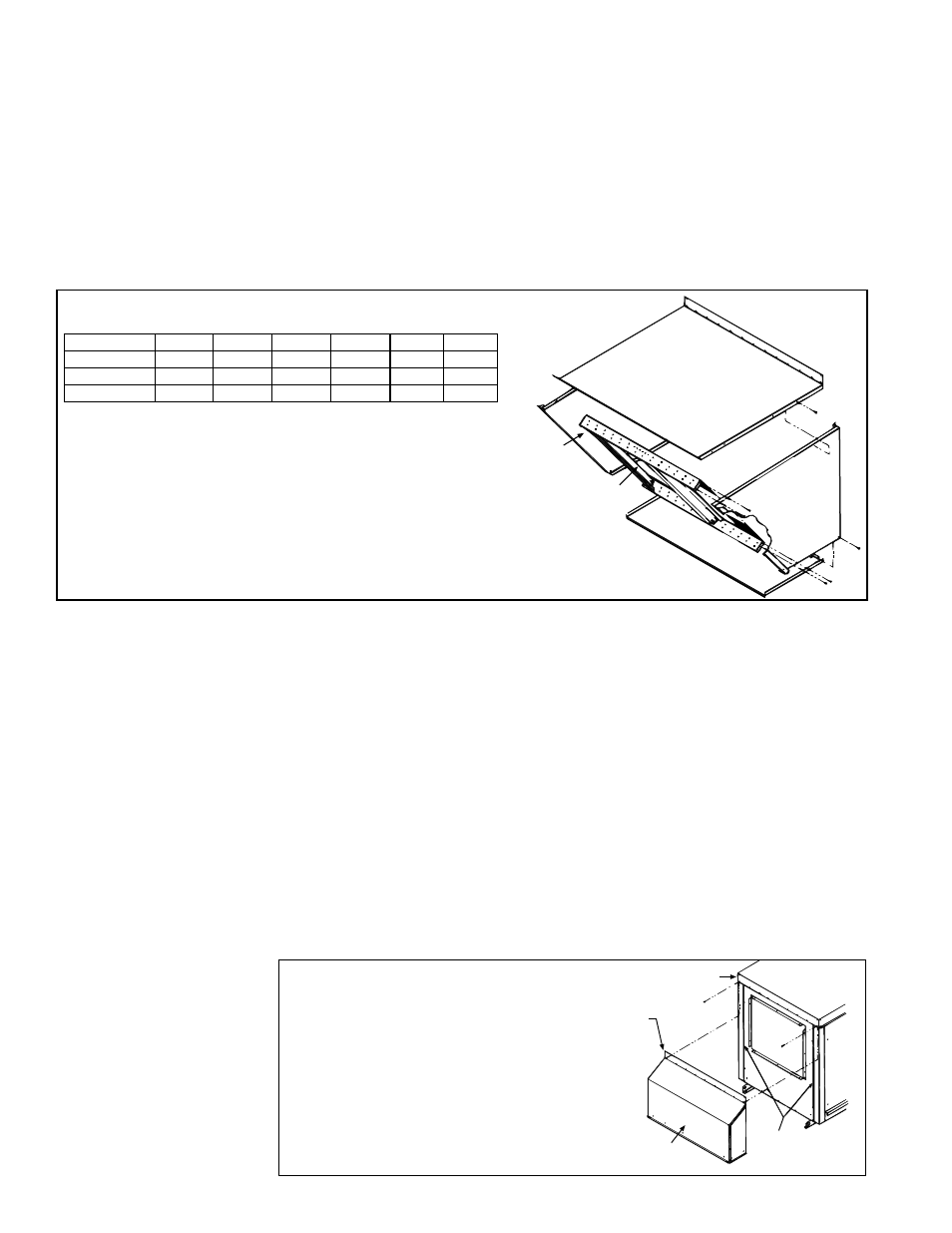
Installation Instructions - Option AS2, 100% Outside Air Hood
Refer to
FIGURE 8. All screw ends except those across the bottom should be inside
the air hood.
To avoid possible damage, it is recommended that the outside air hood be installed
after the system has been placed on the roof. The air hood should be installed before
the heater is operated. Do not install the hood while the system (furnace or blower) is
in operation.
1. Top Panel - On the air inlet side of the blower cabinet, remove the factory-installed
screws attaching the blower cabinet top. Slide the air hood
top panel underneath
the edge of the blower cabinet top.
The edge of the air hood top panel must be
between the blower cabinet top and the end panel. Reinsert all of the sheet-
metal screws.
Top Panel (edge must be
underneath cabinet top)
Left Side
Panel
Right Side
Panel
Factory-assembled Louver Assembly
including Moisture-Eliminating Louvers
and Screen
Bottom Panel
NOTE: Either a manufacturer
designed optional air inlet
hood as shown here or an
evaporative cooling module as
shown in Paragraph 6.3.4 is
required to ensure complete
weather resistance.
FIGURE 8 - Assembly Drawing of Option AS2 Outside Air Hood
6.3.1 Field-Installed
Outside Air Hood
(cont'd)
6.3 Unit Inlet Air
(cont'd)
6.0 Mechanical
(cont'd)
2. Side Panels - Slide the air hood right side panel into the groove in the blower cabinet end panel. Be sure that the
side panel is underneath and to the inside of the air hood top panel. Attach to the blower cabinet and the air hood
top using the required number of sheetmetal screws. Repeat with the left side panel.
3. Bottom Panel - Position the air hood bottom panel so that it is to the inside of the two side panels and above the
factory-installed support angle. Attach to the side panels.
If the bottom panel does not rest tightly against the support angle, follow these instructions to adjust the position of
the support angle:
a) Slightly loosen (do not remove the screws).
b) Slide the support angle up so that it is against the bottom panel.
c) Tighten the screws.
Attach the support angle to the air hood bottom panel. The bottom panel of the air hood and the support angle should
be tight together; do not draw with the sheetmetal screws.
4. Louver Assembly - With the intake screen toward the inside of the hood position the pre-assembled vertical louver
assembly in the inlet opening of the air hood. Using the remaining sheetmetal screws, attach the louver assembly
to the air hood side panels at the holes.
RPB Size
125
150,175 200,225 250,300
350
400
Top Panel
100227 100228 100229 100230 100231 100232
Bottom Panel 100234 100235 100236 100237 100238 100239
Louver Assy
103773 103774 103775 103776 103777 103778
Screened Air Hood
for 30% Outside Air
Opening, Part of Inlet
Air Options AR6 and
AR7
The outside air hood included in the air inlet options that have a 30% outside air open-
ing (Option AR6 or AR7) is shipped separately for field installation. Instructions for
attaching are packaged with the air hood.
FIGURE 9 - Installation
of Air Hood on Cabinets
with 30% Outside Air
Opening Options
Blower
Cabinet
Remove two corner and
compete row of screws.
Slide top
flange
underneath
the cabinet
top.
Vertical Slots -
Slide side flanges
into these slots.
30% Outside
Opening Air Hood
1. On the inlet air side of the blower
cabinet, remove the factory installed
screws attaching the blower cabinet
top.
2. Slide the air hood top flange under-
neath the lip of the blower cabinet
top and the sides into the vertical
slots.
The air hood flange must be
between the blower cabinet top
and the cabinet end panel.
3. Reinsert all of the sheetmetal
screws.