Reznor RPB Unit Installation Manual User Manual
Page 19
Form I-RPB, P/N 131782 R12, Page 19
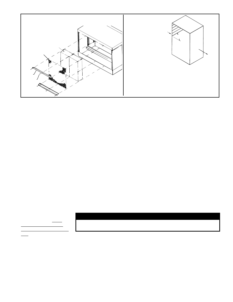
Pad
Screen
Pad
Retainer
Screw
FIGURE 20 - Removal and Replacement of
Evaporative Cooling Module Media
45°
Airflow
to S
pace
Out
side
Airflow
FIGURE 21 -
Media must
be installed
with 45°
angle sloping
downward
toward the
incoming
outside air.
IMPORTANT: The media is made up of two different
sheets of cooling material. Each sheet has its own
unique angle. When replacing the cooling media,
BE CERTAIN that the 45° angle slopes downward
toward the incoming outside air. If the media is not
installed properly, water blowoff from the media
pads will occur.
Instructions for
Replacing Media Pads
1. Remove the three sheetmetal screws that hold the top pad retainer. Release the
top pad retainer from the cooling module.
2. Remove the three sheetmetal screws that hold the bottom pad retainer. Release
the bottom pad retainer from the cooling module.
3. Disengage the inlet screen from media pads and remove.
4. Slide all media pads horizontally away from the cooling module until clear of
bottom reservoir pan. Dispose of properly.
5. Slide media pads over both support rails until back stop is encountered. Media
must be placed as shown in FIGURE 21.
6. Center screen on the incoming air side of the media.
7. Replace the bottom pad retainer by securing the retainer between the pad and the
reservoir pan. Fasten with the three sheetmetal screws removed in Step 2.
8. Replace the top pad retainer by securing the retainer between the pad and top of
the cooling module. Fasten with the three sheetmetal screws removed in Step 1.
Water Feed and
Distribution Line
Annually, the water supply line and the water distribution line (either PVC pipe or water
sock) should be flushed of debris and contaminants.
1. Remove the media pads.
2. Remove the water feed line from the downstream side of the ball valve and
unscrew the water bleed line barbed hose fitting.
3. Force a fresh water supply through the water inlet hose and thoroughly flush the
distribution line.
4. Reassemble being careful to install media with air flow direction as shown in
FIGURE 21.
Water Pump and Inlet
Basket Screen
(Does
not apply to module with
optional timed metering sys-
tem.)
- Annually, the pump
and inlet basket screen
should be removed, disas-
sembled, and cleaned.
WARNING
Do not expose pump motor or any part of the electrical box to
water. Evaporative cooling pump is NOT submersible.
1. Disconnect the power supply to the unit.
2. Remove the service panel and the junction box door. Disconnect the two-line
voltage power supply wires from the terminal block inside the junction box.
3. Disconnect the water feed line hose from the upstream side of the ball valve.
4. Unscrew the four sheetmetal screws holding the junction box to the cooling
module. Remove the junction box-pump-float switch assembly (See
FIGURE 22).
5. Dislodge the inlet basket screen from the pump and clean any buildup of debris
and dirt. Carefully remove the base cover plate from the bottom of the pump.
Using a mild soap solution, wash all deposits from the inside of the pump and
remove all debris from the impeller.
6. Reassemble the pump. Replace the parts in exact reverse order, being careful that
everything is returned to its proper position.